Troubleshooting an Enphase System
2014 Enphase Energy Inc. August 2014
Microinverter and PV Module Issues
This section describes ways to isolate failures within
microinverters or PV modules using:
Microinverter LEDs
Power Production
Microinverter LEDs
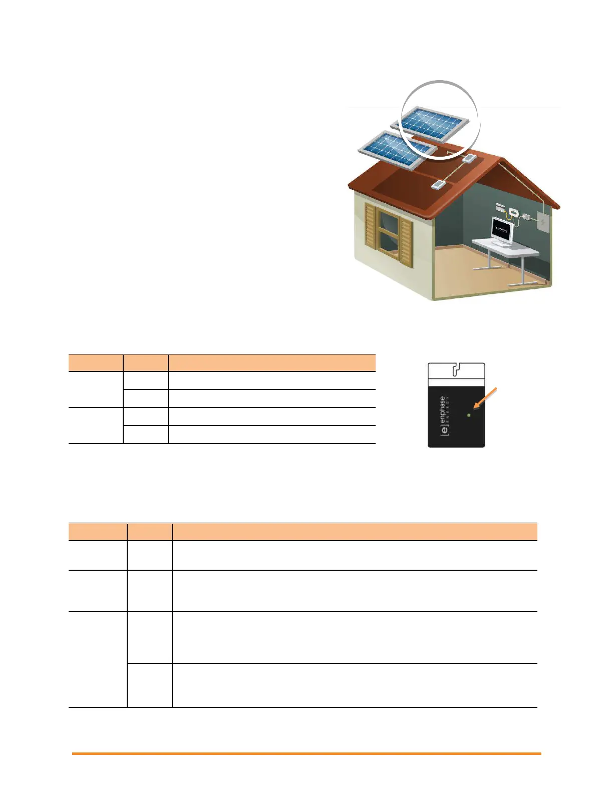
Startup LED Operation
The status LED on the underside of each microinverter
lights green about six seconds after DC power is applied. It
remains lit solid for two minutes, followed by six green
blinks. After that, red blinks indicate that no grid is present if
the system is not yet energized.
Six short red blinks when DC power is first applied to the
microinverter indicate a failure during microinverter startup.
(On older models, including M190, M210, and D380, the LED is on the edge of the microinverter.)
Transition to post start up state
No grid present (AC breaker is not turned on)
Failed microinverter start up
Post-Startup LED Indications
Use a handheld mirror to view indicator lights on the undersides of the microinverters. LED states are:
Normal operation. The microinverter is receiving messages from the Envoy and
senses that the utility grid is within voltage/frequency specifications.
Not receiving messages from the Envoy, but is otherwise operating normally.
The microinverter senses that the utility grid is within voltage/frequency
specifications. Troubleshoot as described in the following sections.
Failed to produce power and not operating normally. The microinverter does
not sense that the utility grid is within voltage/frequency specifications. The
microinverter cannot produce power until this is resolved. . Troubleshoot as
described in the following sections.
Fault requiring intervention.
For M215-60-2LL-S22-IG, S23-IG, or S24-IG this indicates a “DC
Resistance Low – Power Off” fault. (continued on next page)
LED on
underside
of micro-
inverter
 Loading...