28
IP1951EN - 2014-10-06
6. Outputs and accessories
Output
Value /
Accessories
Description
01R+ R- 8A
24 V 0.5 A (max)
Accessories power supply. External accessories power sup-
ply output.
N.B.: the maximum absorption of 0.5 A corresponds to the
sum of all terminals 1.
0121
22
COMER
MD1
Allows connection of the COMER selector and MD1 display
for distances of up to 50 m.
N.B.: use a data transmission type screened cable.
Connect the shielding to the earthing.
N.B.: If firmware needs updating, connect the DMCS device
to the DMCS JACK on the function selector switch. When the
operation has been completed, disconnect the DMCS device
and perform a POWER RESET.
12AB927 29
SELECTOR
COMKR
It allows COMKR selector connection, as described on page
25.
N.B.: connect terminals 21-22 (REMOTE) to the DMCS jack
on the COMKR selector using a data transmission type
shielded cable.
BIXMR2
This allows the functioning configurations to be saved us-
ing the → function of the MD1 display module.
The saved configurations can be recalled via the →
function of the MD1 display module.
If the control panel is replaced, the BIXMR2 storage module
being used can be inserted in the new control panel.
WARNING: the storage module must be inserted and re-
moved with the power supply disconnected.
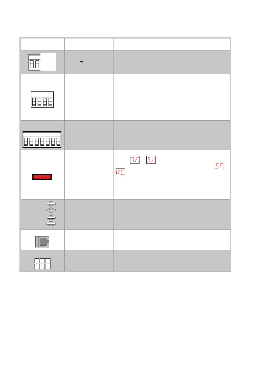
-
MOT
+
-
MOT2
Motor connection.
Connect the double winding motor to the control panel using
the supplied cables as described on pages 24-25.
Encoder connection.
Connect the encoder to the control panel using the supplied
cables as described on pages 24-25.
AL2
Power supply unit connection, as described on pages 24-25.