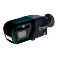
STACK 710 3 Installation Instructions
ENVEA UK Ltd (PC-000878-MA Issue 7, December 2021) 15
3. Installation Instructions
3.1 Installation Checklist
1. Select the installation location.
2. Install the mounting flanges.
3. Install the Air Blower Unit(s) for the purge air supply. Consult the Air Blower
Unit Instruction Manual for full details.
4. An external circuit breaker incorporating over-current protection or a power
isolator and fuse must be fitted to the blower supply.
5. Route all signal and power cables.
6. Connect the power supply to the Air Blower Unit(s).
7. Connect the electrical power supply and signals to the instruments using the
5m (16 ft) pre-terminated cables supplied.
8. Power up the air purge system.
9. Install the Transceiver and Retro-reflector; remember to connect the purge
air supply from the Air Blower Unit(s) before mounting them on the flanges.
10. Power up the instrument and calibrate it.
3.2 Selecting an Installation Location
1. For new plants, the location of the Transceiver should be planned during the
design stages. For existing plants, the best possible location must be
selected. The Transceiver should be mounted so that it measures a
representative concentration of dust across the stack or duct diameter.
2. If the monitor is to be used for US regulatory compliance, the location should
be determined by the EPA installation specifications detailed in 40 CFR 60,
Appendix B, Specification 1, or a location approved by the appropriate
agency. In Europe, the location should the determined in accordance with
EN15259.
3. At the installation location, there should be as much negative pressure as
possible, for example, a stack updraft.
4. The mounting area must have a safe walkway: if necessary, a sufficiently
large and accessible platform should be constructed.
5. The ambient temperature at the mounting location must remain between
-20 °C and +55 °C (-4 °F and 131 °F), or down to -40 °C (-40 °F) with
optional equipment. If necessary, heating, ventilation, or a sun shield should
be used to ensure this temperature range is not exceeded.