EasyManuals Logo

envea STACK 710 User Manual

envea STACK 710
68 pages
To Next Page IconTo Next Page
To Previous Page IconTo Previous Page
Page #17 background imageLoading...
Page #17 background image
STACK 710 3 Installation Instructions
ENVEA UK Ltd (PC-000878-MA Issue 7, December 2021) 17
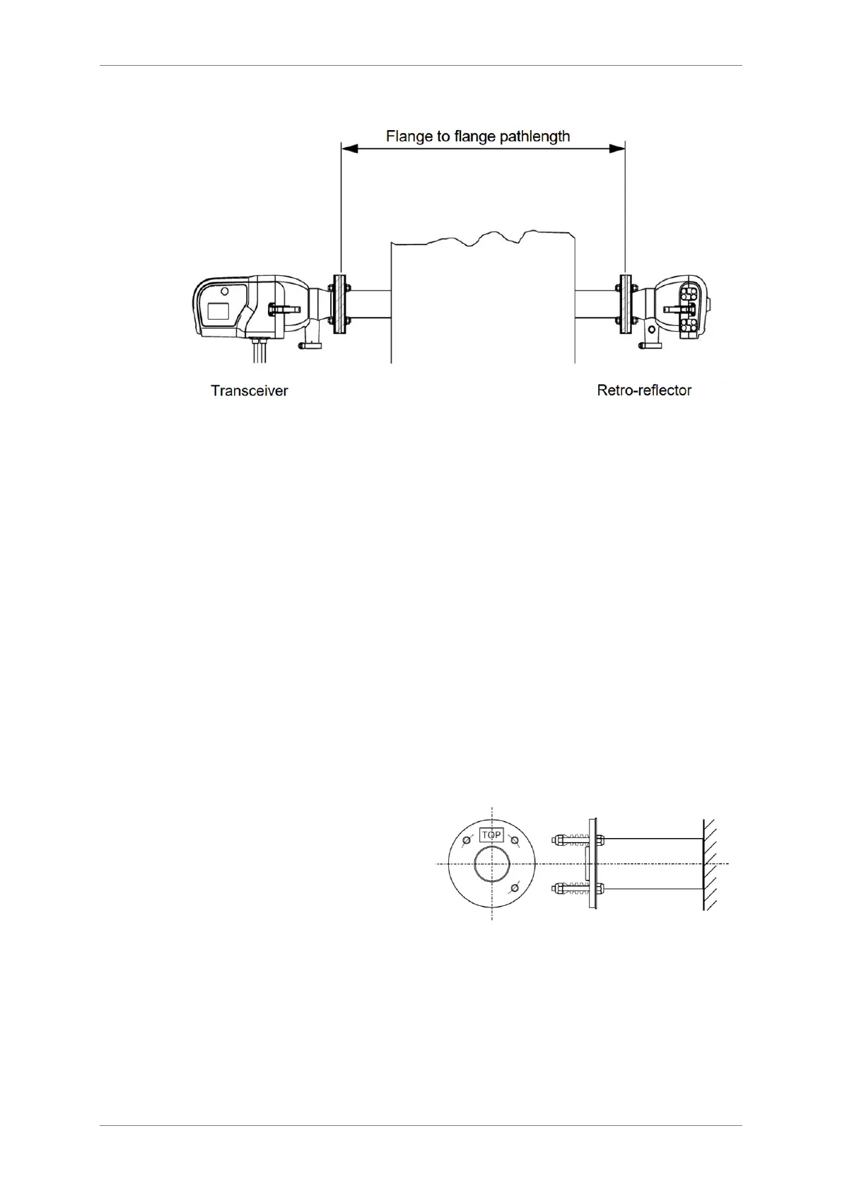
Figure 4: STACK 710- pathlength distance.
3.4 Installing the Mounting Flanges


1. Each sleeve is 128 mm (5.04) long.Adjust the sleeves to obtain the proper
measurement path.
2. Accurately mark the centre of each mounting flange on the stack and punch
a locating mark through the liner onto the inner stack plating.
3. On both sides of the stack, cut a hole from the liner large enough to allow
welding of the mounting flange to the stack.
4. Where the Transceiver will be installed, cut a hole through the stack at the
punched location mark.
5. Where the Retro-reflector will be installed, make a 6 mm to 12 mm diameter
pilot hole (0.25 to 0.50)
6. Position the Transceiver
mounting flange with the 
label in the 12 
and tack weld the mounting
flange in place.
Figure 5 Mounting flange schematic.




Table of Contents

Questions and Answers:

Question and Answer IconNeed help?

Do you have a question about the envea STACK 710 and is the answer not in the manual?

envea STACK 710 Specifications

General IconGeneral
Brandenvea
ModelSTACK 710
CategoryMeasuring Instruments
LanguageEnglish