Do you have a question about the envea STACK 710 and is the answer not in the manual?
Details the objective and scope of the user manual for the STACK 710 instrument.
Provides guidance on safely lifting and moving the STACK 710 instrument.
Explains the meaning of various safety and operational symbols used on the device.
Highlights health and safety risks associated with process particulates and gases.
Information on available components, accessories, and optional features for the STACK 710.
Details the instrument's compliance with relevant environmental and safety standards.
Specifies the DC voltage and current required for operating the STACK 710.
Describes the configurable current loop output functions for data reporting.
Explains the function of the system status, calibration, and alarm indicator LEDs.
Details how to connect the STACK 710 to a computer or data acquisition system.
Visual representation of the STACK 710 system components and their arrangement.
A step-by-step guide to ensure all installation tasks are completed correctly.
Criteria and considerations for choosing the optimal mounting location for the instrument.
Instructions on ensuring the correct pathlength is maintained during the installation process.
Procedure for correctly fitting the mounting flanges to the stack or duct.
Specifics regarding mounting components, including air purge connections.
Guidance on using the alignment tool for precise flange positioning.
Important considerations and clearances required for installing optical components.
Detailed steps for physically mounting the main instrument components.
Instructions for connecting power and signal cables to the instrument.
Pin assignments and wiring details for the transceiver connectors.
Procedures for linking the STACK 710 to the ENVEA control system.
Recommended cable types and specifications for system integration.
System requirements and details for the PC-ME DUST TOOLS software.
Overview of the instrument's control panel, display, and indicators.
Explanation of the keypad functions for operating the instrument.
A guide to the icons and symbols used within the STACK 710 interface.
Definitions of technical terms and abbreviations used in the manual.
Steps for initial setup and verification of the STACK 710 upon first use.
Procedure for accurately aligning the retro-reflector component.
Procedure for accurately aligning the transceiver component.
Configuring the frequency for automatic calibration checks.
Configuring the instrument's analogue output for data transmission.
Setting alarm thresholds and parameters for process deviations.
Performing a routine check to verify the instrument's calibration status.
Details on configuring and using the Modbus communication protocol.
Explains how to apply scaling factors to interpret Modbus register values.
Lists useful read-only registers and their corresponding data.
Describes the two-step process for periodically checking instrument calibration.
Procedures for conducting calibration audits as required by regulatory authorities.
Steps to perform a clear stack calibration when no smoke or dust is present.
Guidance on performing gravimetric (isokinetic) calibration for dust density.
Instructions for manually entering calibration constants to recover from miscalibration.
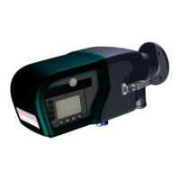
Provides an overview of the STACK 710's function and components.
Details the fundamental scientific principle behind opacity measurement.
Explains the PLCF used to adjust opacity readings based on stack dimensions.
Illustrates how different stack configurations affect the PLCF value.
Outlines the instrument's compliance with environmental regulations and standards.
Technical specifications including measuring range, resolution, and operating parameters.
Guide to accessing and interpreting diagnostic information for troubleshooting.
A list of fault codes, their descriptions, and recommended corrective actions.
Recommended periodic maintenance tasks to ensure optimal instrument performance.
Instructions for cleaning the transceiver and retro-reflector optical components.
Procedure for safely removing and replacing the transceiver cover for internal access.
A sheet for documenting instrument settings, serial numbers, and service history.
| Manufacturer | ENVEA |
|---|---|
| Gases Measured | CO2, CO, O2, NO, NO2, SO2 |
| Measurement Range (O2) | 0-25 % |
| Measurement Range (NO) | 0-500 ppm |
| Operating Temperature | -20°C to +50°C |
| Outputs | 4-20 mA, Digital Outputs |
| Enclosure Rating | IP65 |
| Dust Measurement | Optional |
| Flow Measurement | Optional |
| Compliance | EN 15267 |
| Data Acquisition System | Integrated |
| Communication | Modbus, Ethernet, RS485 |
| Power Supply | 100-240 VAC, 50/60 Hz |
| Measurement Principle | NDIR (CO2, CO) |
| Measurement Range (CO2) | 0-25% |
| Accuracy (CO2) | < 2% of reading |
| Accuracy (CO) | < 2% of reading |
| Accuracy (O2) | < 2% of reading |
| Accuracy (NO) | < 2% of reading |
| Accuracy (NO2) | < 2% of reading |
| Accuracy (SO2) | < 2% of reading |
| Dimensions | 600 x 300 mm |
| Weight | 30 kg |