EasyManuals Logo

envea STACK 710 User Manual

envea STACK 710
68 pages
To Next Page IconTo Next Page
To Previous Page IconTo Previous Page
Page #16 background imageLoading...
Page #16 background image
3 Installation Instructions STACK 710
16 (PC-000878-MA Issue 7, December 2021) ENVEA UK Ltd
6. If the duct walls are too thin to support the instrument's weight, additional
reinforcement will be required.
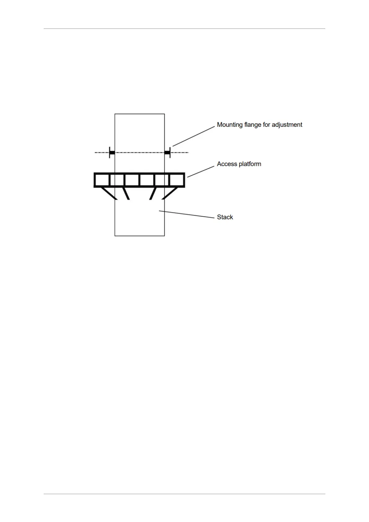
7. The mounting flanges must be positioned such that the Transceiver and
Retro-reflector face each other across the centre of the stack or duct. Since
most applications involve a vertical stack, the axis common to both flanges
must be level and perpendicular to the direction of gas flow.
Figure 3: STACK 710- installation schematic
3.3 Maintaining the pathlength during installation






            


Table of Contents

Questions and Answers:

Question and Answer IconNeed help?

Do you have a question about the envea STACK 710 and is the answer not in the manual?

envea STACK 710 Specifications

General IconGeneral
Brandenvea
ModelSTACK 710
CategoryMeasuring Instruments
LanguageEnglish