3 Installation Instructions STACK 710
18 (PC-000878-MA Issue 7, December 2021) ENVEA UK Ltd
7. Cut a hole around the Retro-reflector pilot hole, large enough to allow
eventual welding of the outsideof the flange stub to the stack wall. The
mounting flange plate must be parallel to the stack wall.
8. If the measuring path is short (under 2m / 6.5ft) and easily accessible the
flanges can be aligned using a straight piece of tube.
8a. Slide the tube through both flanges., ensuring that the specified flange-
to-flange measuring path is maintained to within ±1%.
8b. Tack weld the Retro-reflector mounting flange in place.
8c. Make any necessary adjustments to the Transceiver mounting flange
8d. to ensure alignment between the two flanges is maintained. Weld the
flange permanently in place.
8e. Make any necessary adjustments and weld the Retro-reflector mounting
flange permanently in place.
3.5 Mounting Details
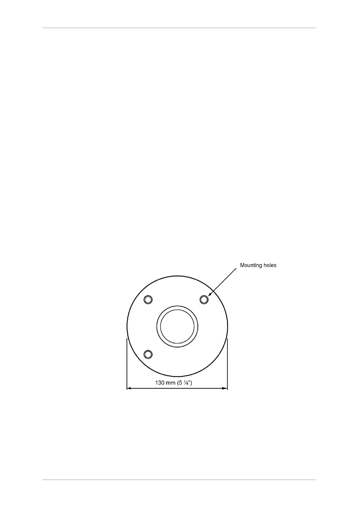
3.5.1 Air Purge Mounting Holes
Figure 6: Front view of Air Purge showing mounting holes.
3.6 Flange Alignment Tool