STACK 710 3 Installation Instructions
ENVEA UK Ltd (PC-000878-MA Issue 7, December 2021) 19
3.7 Important information for installing the Transceiver and
Retro-reflector
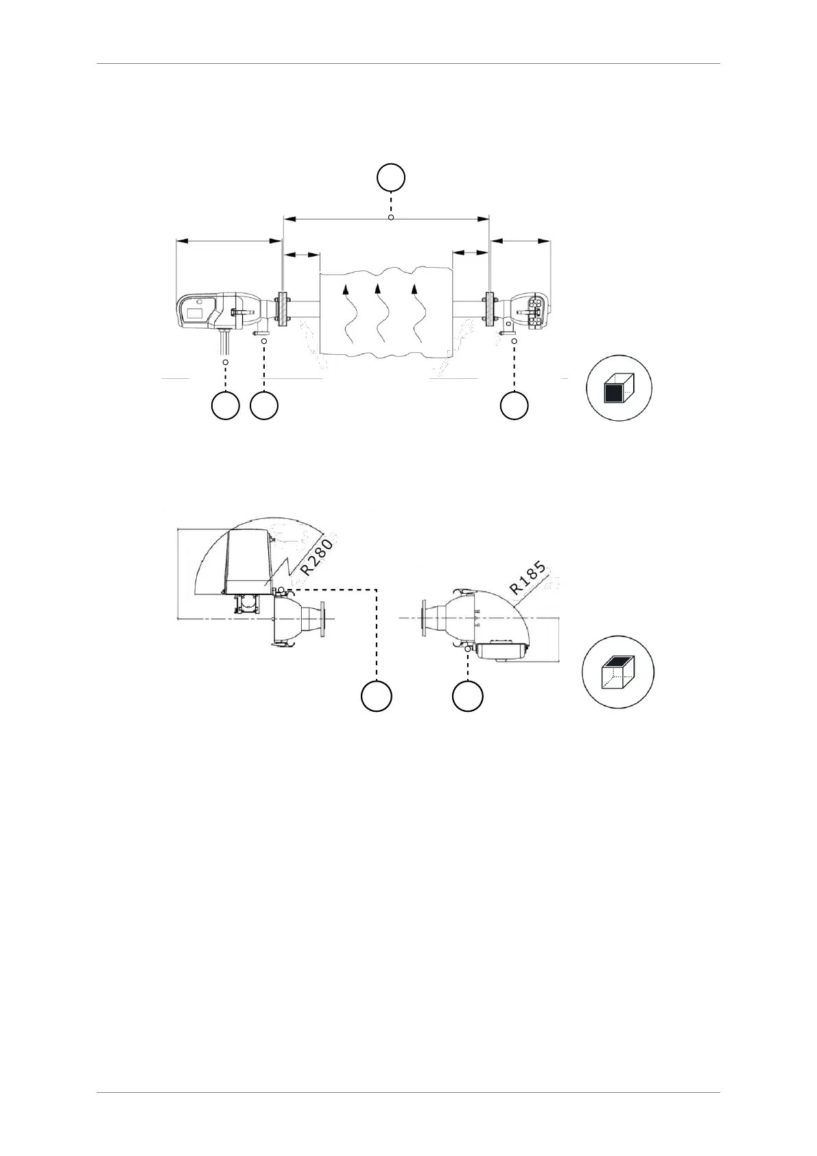
Figure 7: Installing the Transceiver and Retro-reflector (side view).
Figure 8: Installing the Transceiver and Retro-reflector (top view).
1. Check the dimensions carefully before installation.
1a. Allow at least 1 m (3.3 ft) for mounting and removal procedures
1b. Allow a minimum of 200 mm (7.) directly below the instrument for
purge air (3) and electrical connections (4).
1c. Allow sufficient space to the side of each instrument to allow the hinges
(6 and 7) to be opened.
1d. Check the Blower Unit Manual for additional installation requirements.
2. The air hose fitted between the air blower unit (see the diagram in section
A2) and its two connections on the instrument (3) must not exceed 7m (23
ft).