3 Installation Instructions STACK 710
20 (PC-000878-MA Issue 7, December 2021) ENVEA UK Ltd
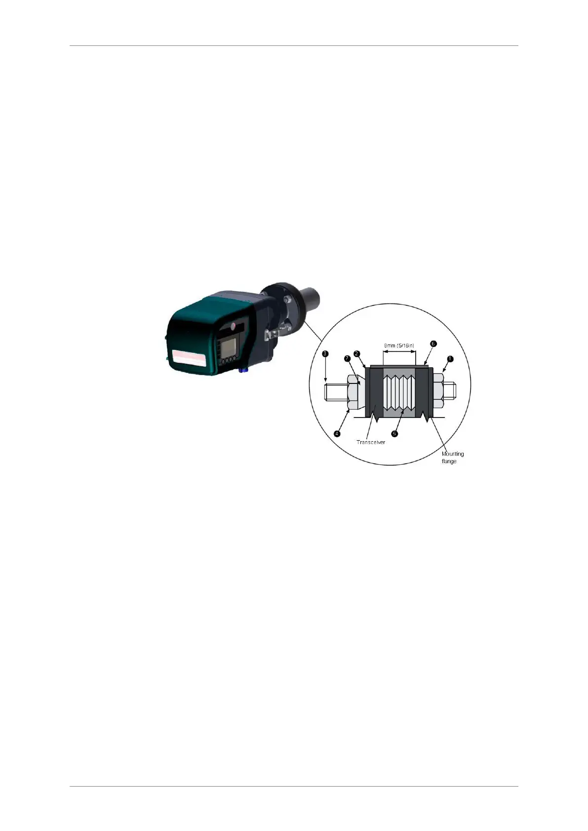
3. The flange-to-flange path length (5) is factory set and must not be changed.
It is given on the back of the Transceiver.
4. Pre-terminated 5 m power and data cables are supplied with this
instrument.
3.8 Mounting the Transceiver and Retro-reflector
1. Ideally, the instrument should be installed when the process is not operating
and the stack is cold.
2. The air blower unit should be operating and connected to the Transceiver
and Retro-reflector before the instrument is mounted onto the flanges.
3. Check that each mounting stud has four pairs of spring washers (5)
arranged as shown - these may have been removed if the flange alignment
tool was used.
Figure 9: Mounting the Transceiver and Retro-reflector.
4. Place a rubber sealing band over the mounting flanges for the Transceiver
and Retro-reflector.It cannot be fitted after the instrument is mounted on
the flange.
5. Remove the three M10 nuts (4) and dome washers (2) from the mounting
flange, and locate the Transceiver onto the studs (3).
6. Replace the Nyloc nuts (4) and dome washers (2) and tighten them,
compressing the spring washers (5) until there is a gap of 11 mm ()
between the two flanges, all round. Pull the sealing band (6) into place over
the gap.
7. Install the Retro-reflector following the same procedure.