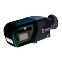
STACK 710 4 Getting Started
ENVEA UK Ltd (PC-000878-MA Issue 7, December 2021) 33
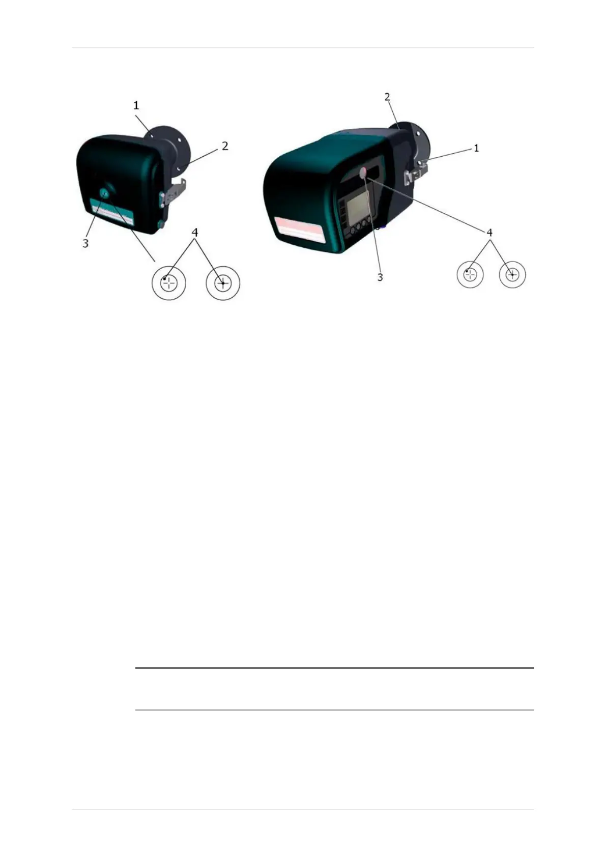
Figure 15: Aligning the Retro-reflector.
4.7 Align the Transceiver
1. Observe the alignment target through the window (3). A bright green spot
(4) should be visible.
2. To move the green spot horizontally, adjust M10 nut (1) on the air purge
flange and to move it vertically, adjust the M10 nuts (2), also on the air
purge flange as illustrated in . Adjust these nuts until the green
spot is inside the inner circle.
3. In bright sunshine, the green spot on the alignment target may not be
visible. In this case, return to the Retro-reflector, undo the quick-release
clamps and swing open the rear cover. It should now be possible to adjust
the Transmissometer until the bright circle of sunlight visible through the
Retro-reflector purge unit is centred on the target. Close the Retro-reflector
again. If the green spot is visible, adjust the nuts until it is central in the
inner circle.
4. Ensure that the 4 pairs of spring washers between the air purge flange and
the mounting flange are under moderate compression. If the compression
becomes excessive, the third nut has likely been over tightened, or the
mounting flange may not have been fitted accurately.
Note: If any of the settings are changed from their default values, the new values
should be noted on the Calibration Report and Settings List supplied with the
instrument.