13
ENVISION RESIDENTIAL INSTALLATION MANUAL
Electrical Connections
General
Be sure the available power is the same voltage and phase as that shown on the unit serial plate. Line and low voltage
wiring must be done in accordance with local codes or the National Electric Code, whichever is applicable.
Unit Power Connection
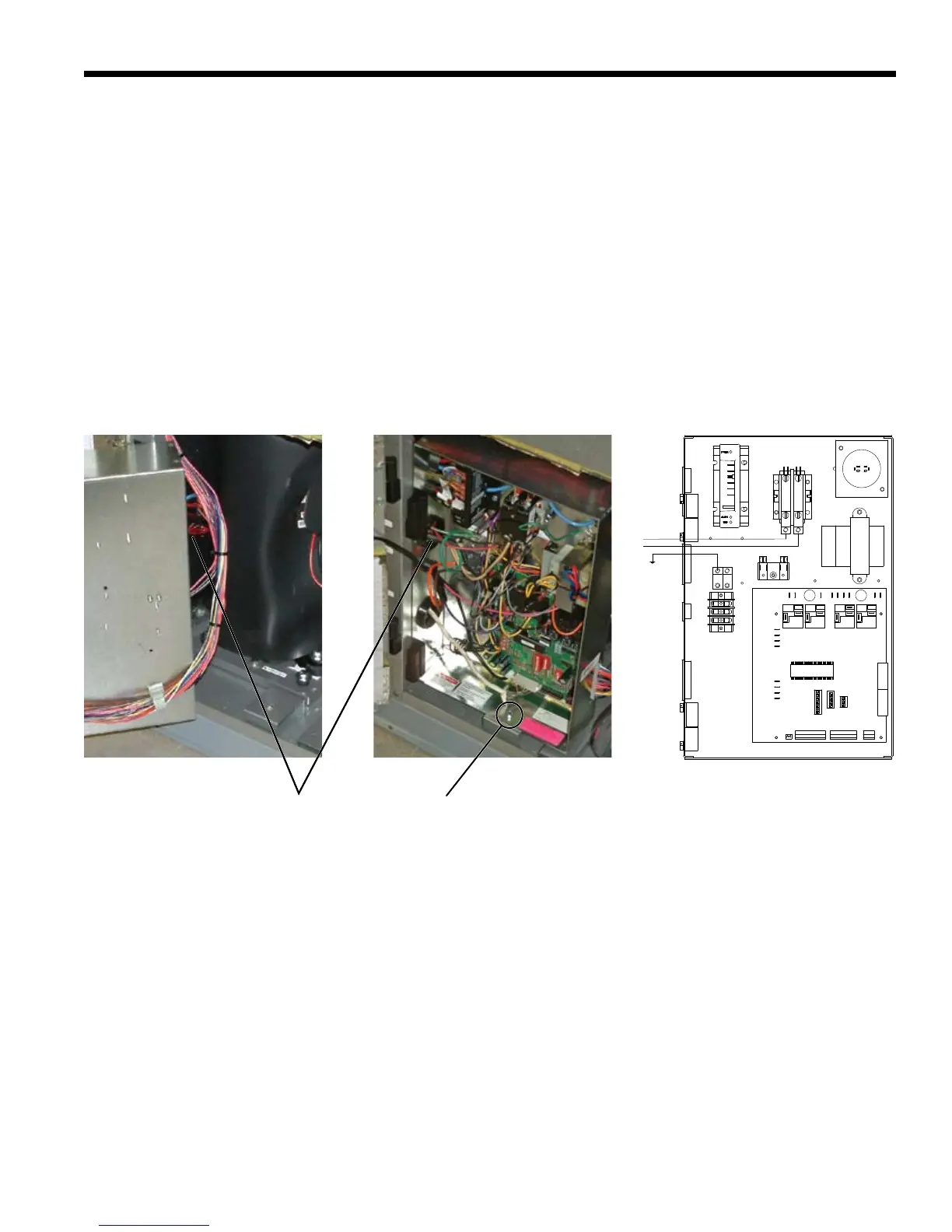
ConnecttheincominglinevoltagewirestoL1andL2ofthecontactorasshowninFigure13Cforsingle-phaseunit.Consult
theUnitElectricalDataintheSpecicationCatalogforcorrectfusesizes.
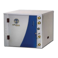
Openlowerfrontaccesspanel.Removegroundfastenerfrombottomofcontrolbox(Figure13B).Swingopencontrolbox
(Figure13A).Insertpowerwiresthroughknockoutsonlowerleftsideofcabinet.Routewiresthroughleftsideofcontrolbox
andconnecttocontactorandground(Figure13C).Closecontrolboxandreplacegroundingfastenerbeforeunitstart-up.
Accessory Relay
A set of “dry” contacts has been provided to control accessory devices, such as water solenoid valves on open loop instal-
lations,electronicaircleaners,humidiers,etc.Thisrelaycontactshouldbeusedonlywith24voltsignalsandnotlinevoltage
power. The relay has both normally open and normally closed contacts and can operate with either the fan or the compressor.
UseDIPswitchSW2-3tocycletherelaywithfanorcompressor.Therelaycontactsareavailableonterminals#2and#3of
P3.
208 Volt Operation
AllEnvision208/230unitsarefactorywiredfor230voltoperation.For208voltoperation,theredandbluetransformer
wires must be switched on terminal strip PS.
GroundFastenerWire Insert
Location
Figure 13C:
LineVoltage208-230/60/1controlbox
Figure 13B:
Wire access (control box closed)
Figure 13A:
Wire access (control box open)
 Loading...