14
ENVISION RESIDENTIAL INSTALLATION MANUAL
Auxiliary Heat Ratings
KW BTU/HR Min Envision Series Compatibility
Model 208V 230V Stages 208V 230V CFM 022 026 - 030 036 - 049 060 - 072
EAM(H)5 3.6 4.8 1 12,300 16,300 450
• •
EAM(H)8 5.7 7.6 2 19,400 25,900 550
• •
EAM(H)10 7.2 9.6 2 24,600 32,700 650
•
EAL(H)10 7.2 9.6 2 24,600 32,700 1100
• •
EAL(H)15 10.8 14.4 3 36,900 49,100 1250
• •
EAL(H)15-3 10.8 14.4 3 36,900 49,100 1250
• •
EAL(H)20 14.4 19.2 4 49,200 65,500 1500
•
"H" is used in part number for horizontal units
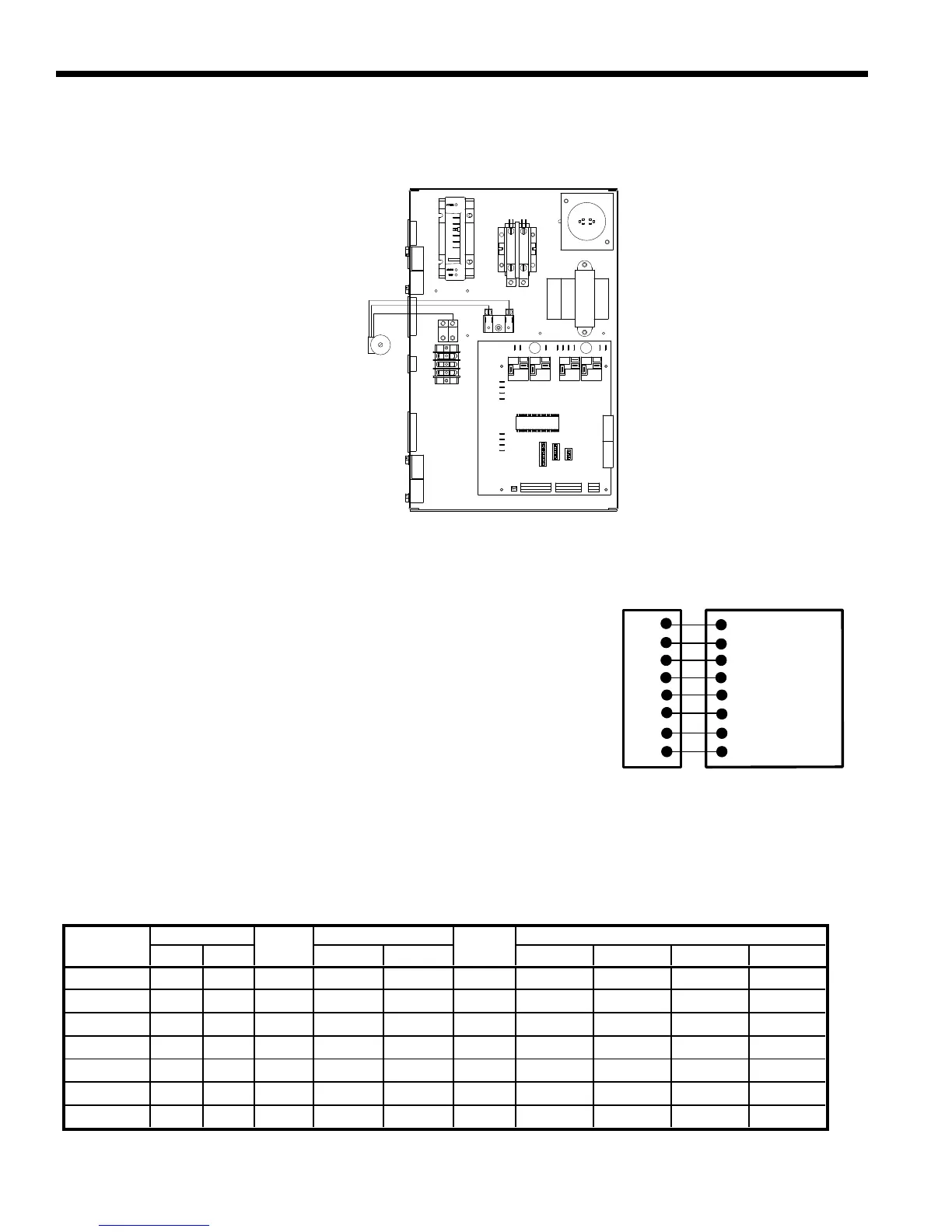
Electrical Connections (cont.)
Pump Wiring
SeeFigure14forelectricalconnections
from control box to pumps.
Electronic Thermostat
Position the thermostat subbase against the wall so that it is level and the
thermostat wires protrude through the middle of the subbase. Mark the position
ofthesubbasemountingholesanddrillholeswitha3/16-inchbit.Installsupplied
anchorsandsecurebasetothewall.Thermostatwiremustbe8-conductor,18-
AWGwire.Stripthewiresback1/4-inch(longerstriplengthsmaycauseshorts)
and insert the thermostat wires into the connector as shown. Tighten the screws
to insure secure connections. The thermostat has the same type connectors,
requiring the same wiring. See instructions enclosed in the thermostat for detailed
installation and operation information.
Note: DIPswitchSW2-8isrequiredtobeinthe“OFF”positionforthecontrol
tooperatewithFaultFlashorComforTalkthermostats.SW2-8inthe“ON”positionconguresthecontroltooperatewith
typicalthermostats(continuouslockoutsignal).TheremustbeawireconnectingY2onthemicroprocessorcontrollerto2nd
stage compressor on the thermostat for proper operation.
Figure 14: Pump Wiring 208-230/60/1
Figure 15: Thermostat Wiring
R
Y1
C
W
O
G
L
24VAC (Hot)
24VAC (Common)
Compressor (1st Stage)
Aux. Heat
Reversing Valve
Blower Relay
System Monitor
Microprocessor Controller
Thermostat Connection
Y2
Compressor (2nd Stage)
 Loading...