38
ENVISION RESIDENTIAL INSTALLATION MANUAL
Troubleshooting
Standard Microprocessor Controls
To check the unit control board for proper operation:
1) Disconnectthermostatwiresatthecontrolboard.
2) Jumperthedesiredtestinput(Y1,Y2,W,OorG)totheRterminaltosimulateathermostatsignal.
3) If control functions properly:
• Checkforthermostatandeldcontrolwiring(usethediagnosticinputsmode).
4) Ifcontrolrespondsimproperly:
• Ensurethatcomponentbeingcontrolledisfunctioning(compressor,blower,reversingvalve,etc.).
• Ensurethatwiringfromcontroltothecomponentisfunctioning(refertotheLEDDenitiontablebelowandusethe
diagnostic outputs mode).
• Ifstepsabovecheckproperly,replaceunitcontrol.
Refrigerant Systems
To maintain sealed circuit integrity, do not install service gauges unless unit operation appears abnormal. Compare the
changeintemperatureontheairsideaswellasthewatersidetothetablesonpages35-36.Iftheunit’sperformanceisnot
withintherangeslisted,andtheairowandwaterowareknowntobecorrect,gaugesshouldthenbeinstalledandsuper-
heat and subcooling numbers calculated. If superheat and subcooling are outside recommended ranges, an adjustment to
the refrigerant charge may be necessary.
Note:
Refrigerant tests must be made with desuperheater turned “OFF”.
Verifythatairandwaterowratesareatproper
levels before servicing the refrigerant circuit.
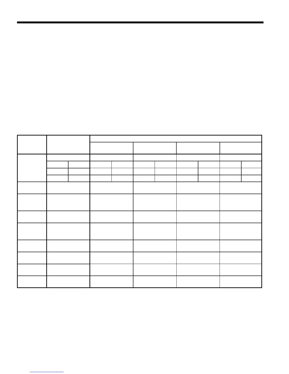
LED
NORMAL
DISPLAY MODE
DIAGNOSTIC MODES
CURRENT
FAULT STATUS
INPUTS OUTPUTS 1 OUTPUTS 2
Field Selection DIPS
SW2- 1On SW2- 1Off SW2- 1NA SW2- 1NA SW2- 1NA
SW2- 6On SW2- 6On SW2- 6Off SW2- 6On SW2- 6Off
SW2- 7On SW2- 7On SW2- 7On SW2- 7Off SW2- 7Off
Drain
DrainPanOverow
Lockout
DrainPanOverow Y1
Compressor
(On or Low)
Blower
Low
Water Flow
FP Thermistor (Loop
<15ºF,Well<30ºF)
Lockout
FP Thermistor (Loop
<15ºF,Well<30ºF)
Y2
Compressor
(On or High)
Blower
Medium
High
Pressure
HighPressure>600
PSI Lockout
HighPressure>600 O Reversing Valve
Blower
High
Low
Pressure/
Compressor
LowPressure<40
PSI Lockout or
Comfort Alert
LowPressure<40
or Comfort Alert
G Fan AuxHeat1
Airow
ECM2RPM<100
RPM
ECM2RPM
<100RPM
W DHW Pump AuxHeat2
Status
Microprocessor
Malfunction
Not Used SL1 Loop Pump(s) Aux Heat 3
DHW Limit
HWL Thermistor
>130º
HWL Thermistor
>130°F
Not Used – AuxHeat4
DHW Off
DHW Pump
Switch Off
DHW Pump
Switch Off
– – –
LED Denitions and Diagnostics
Standard Microprocessor
 Loading...