17
ENVISION RESIDENTIAL INSTALLATION MANUAL
Setting Fan Speed - ECM
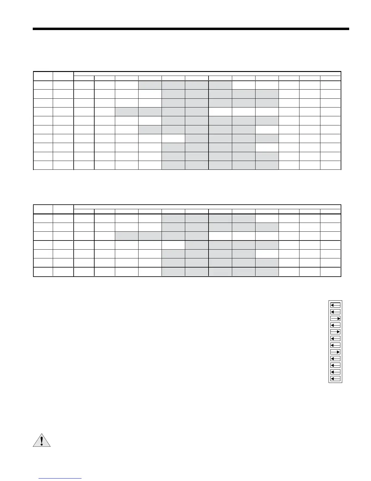
ECM2fanmotorshavea12-speedselectordipswitchonthelogicboard(SW1)andarefactorysetforoptimumperfor-
mance.Tochangespeeds,selecttheappropriatespeedsondipswitchSW1.ConsulttheECM2fanperformancetable
belowforspecicairowandswitchinformation.
CAUTION: Disconnect all power before performing this operation.
Fan Performance Data - ECM
ECM2
A12-positionDIPswitchpackageonthecontrolallowstheairowlevelstobesetforlow,medium,andhigh
speedwhenusingtheECM2blowermotor.OnlythreeoftheDIPswitchescanbeinthe"on"position.
Therst"on"switch(thelowestpositionnumber)determinesthelowspeedfansetting.•
Thesecond"on"switchdeterminesthemediumspeedfansetting.•
Thethird"on"switchdeterminesthehighspeedfansetting.•
TheexampletotherightshowsSW1onthecontrolboardconguredforthefollowingNS042airowsettings.
LowSpeedFan:900CFM•
MediumSpeedFan:1150CFM•
HighSpeedFan:1450CFM•
Single Speed
Dual Capacity
MAX AIR FLOW DIP SWITCH SETTINGS
ESP 1 2 3 4 5 6 7 8 9 10 11 12
400 500 600 700
800 900 1000 1100 1200
L M
H
400 500 600 700
800 900 1000 1100 1200
L M
H
650 750 850 1000 1100 1200
1300 1400 1500
L
M H
036
800 1000 1100 1300 1500 1600
1800
w/1hp*
L M H
650
800 900 1050 1150 1250 1350 1450 1550
L
M H
042
800
900 1000 1200 1400 1600 1700 1850 2000 2200 2300 2400
w/1hp* L M
H
650
800 900 1050 1150 1250 1350 1450 1550
L
M H
048
800
900 1000 1200 1400 1600 1700 1850 2000 2200 2300 2400
w/1hp*
L M H
800
950 1100 1300 1500 1750 1950 2100 2300
L
M H
800
950 1100 1300 1500 1750 1950 2100 2300
L
M H
5/30/06
Factory settings are at recommended L-M-H DIP switch locations CFM is controlled within ±5% up to the maximum ESP
M-H settings MUST be located within boldface CFM range Max ESP includes allowance for wet coil and standard filter
Lowest and Highest DIP switch settings are assumed to be L and H respectively
MAX AIR FLOW DIP SWITCH SETTINGS
ESP 1 2 3 4 5 6 7 8 9 10 11 12
400 500 600 700
800 900 1000 1100 1200
L M
H
650 750 850 1000 1100 1200
1300 1400 1500
L
M H
038
800 1000 1100 1300 1500 1600
1800
w/1hp*
L M H
650
800 900 1050 1150 1250 1350 1450 1550
L
M H
049
800
900 1000 1200 1400 1600 1700 1850 2000 2200 2300 2400
w/1hp*
L
M H
800
950 1100 1300 1500 1750 1950 2100 2300
L M
H
800
950 1100 1300 1500 1750 1950 2100 2300
L
M H
5/30/06
Factory settings are at recommended L-M-H DIP switch locations CFM is controlled within ±5% up to the maximum ESP
M-H settings MUST be located within boldface CFM range Max ESP includes allowance for wet coil and standard filter
Lowest and Highest DIP switch settings are assumed to be L and H respectively
MODEL
022 0.50
026 0.50
0.75
030 0.50
036 0.50
0.75
042 0.50
0.75
048 0.50
MODEL
070 0.75
060 0.75
049 0.50
0.75
038 0.50
0.75
072 0.75
064 0.75
 Loading...