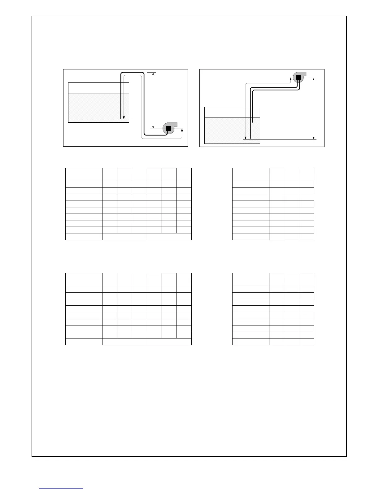
OIL SUPPLY LINE TABLES
One-pipe system Two-pipe system
Kerosene 2.15 mm
2
/s (cSt) Kerosene 2.15 mm
2
/s (cSt)
Gas Oil 6.00 mm
2
/s (cSt) Gas Oil 6.0 mm
2
/s (cSt)
These tables are shown merely as guidance for the suitability of the oil supply
line installation. The typical pipe system used for the calculations comprises – 1
x check valve, 1 x cut off valve, 1 x in-line filter and 4 x 90º elbows
H Ø4
Ø5
Ø6 Ø5 Ø6 Ø8
m mm
mm mm mm mm mm
4.0 66 100 100 33 80 100
3.5 57
100 100
29 70 100
3.0 49
100 100
25 60 100
2.5 41
100 100
20 50 100
2.0 33 80
100
16 40 83
1.5 25 60
100
12 30 62
1.0 16 40 83 8 20 41
0.5 8 20 41 4 10 20
Nozzle capacity 5.0 kg/h 10.0 kg/h
L
H
L
H
H Ø4
Ø5
Ø6 Ø5 Ø6 Ø8
m mm
mm mm mm mm mm
4.0 26 60 100 31 62 100
3.5 22
51 100
27 55 100
3.0 19
44 94
23 47 100
2.5 16
37 78
20 39 100
2.0 13 30
62
16 31 98
1.5 10 22
47
12 23 74
1.0 6 15 31 8 15 49
0.5 3 7 15 4 7 24
Nozzle capacity 5.0 kg/h 10.0 kg/h
H
Ø6
Ø8 Ø10
m mm
mm mm
-0.0 17 53 100
-0.5 15
47 100
-1.0 13
41 99
-1.5 11
34 84
-2.0 9 28
68
-2.5 7 22
53
-3.0 5 15 37
-3.5 — 9 22
-4.0 — — 6
H
Ø6
Ø8 Ø10
m mm
mm mm
-0.0 54 100 100
-0.5 48
100 100
-1.0 42
100 100
-1.5 36
100 100
-2.0 30 94
100
-2.5 24 75
100
-3.0 18 55 100
-3.5 11 36 88
-4.0 5 16 40
E90-803-001-001-00 - 04/06
13