BURNER INSTALLATION
Electrical Connection
The electrical connections to this burner must be
carried out by a suitably qualified engineer.
All Electrical connections to the burner must be
carried out in accordance with all current
applicable IEE Wiring Regulations.
All connections should be made according to the
wring diagram shown on the supplementary page -
page 20 within the manual.
If the burner is fitted with a 7-pin socket and
supplied with the matching plug then all
connections therefore are made within the 7-pin
plug.
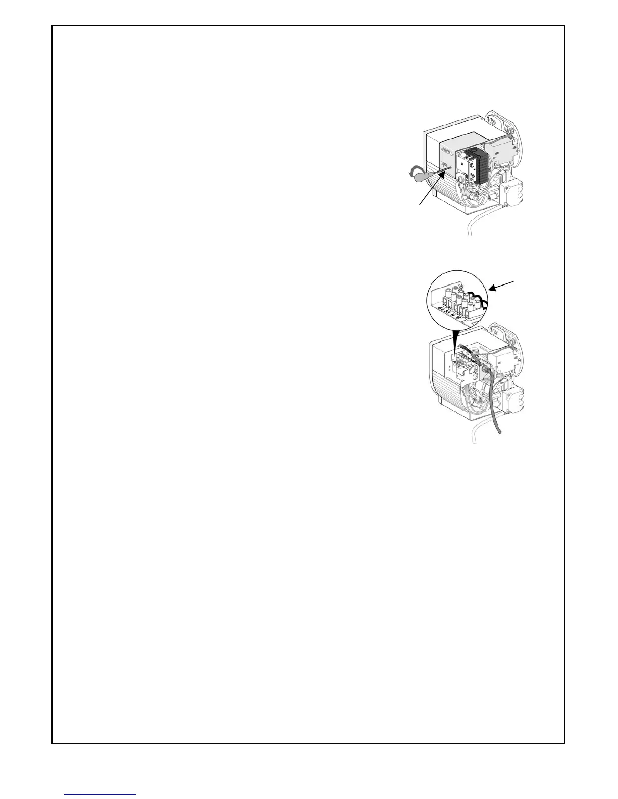
To gain access to the electrical connection strip the
cover must be removed by means of undoing the
3mm Allen screw. Once undone the cover can be
removed exposing the connection strip.
Fuel Supply
The burner is usually supplied for one-pipe operation
but if required can be converted for a two-pipe system (see page 10 for
details). When used in conjunction with a gravity feed supply the inlet pressure
to the pump MUST NOT exceed 2 bar.
When using a two-pipe system the return line has to be fed back into the
tank. Alternatively, a de-aeration device could be incorporated for ease of
installation.
Oil lines must be completely air-tight and constructed in accordance with
current standards.
The final connection to the oil pump must be made with the flexible oil line
provided.
Air Supply
Combustion air and ventilation requirements are detailed in BS5410:Part1. It
requires that combustion air must be provided through purpose-made non-
closeable openings, having a total free area of 550mm2 per kW of the
appliance maximum output rating above 5kW.
Cover fixing