EasyManua.ls Logo

Epever IP350-12 - Communication, Mode, and Status Indicators

Epever IP350-12
24 pages
Print Icon
To Next Page IconTo Next Page
To Previous Page IconTo Previous Page
Loading...
10
(4) RS485 communication port(IP1000 and above models optional)
The RJ45 interface pin definition is shown below:
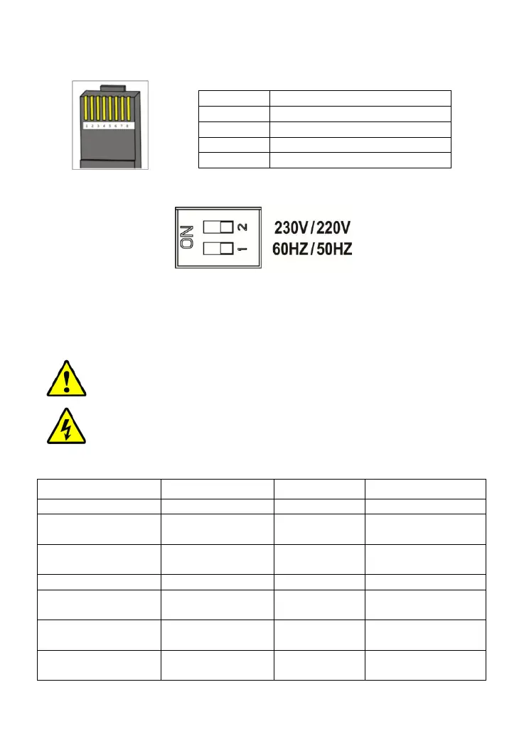
(5) Mode Switch
When the switch No.1 is on the ON side, output frequency is 60Hz, otherwise
is 50Hz.
When the switch No.2 is on the ON side, the output voltage is 230VAC,
otherwise is 220VAC.
NOTE: Both the output frequency and the output voltage
change availability after restart the inverter.
WARNING: DO NOT turn ON/OFF the mode switch when the
inverter is working.
(6) LED indicator and Buzzer
Working indicator
Fault indicator
Buzzer
Status
Green On Solid
Red OFF
No Sounding
Output is normal
Green Slowly
Flashing(1/4Hz)
Red OFF
Sounding
Input under
voltage
Green Fast
Flashing(1Hz)
Red OFF
Sounding
Input over voltage
Green On Solid
Red On Solid
Sounding
Over temperature
Green OFF
Red Fast
Flashing(1Hz)
Sounding
Load short circuit
Green On Solid
Red Slowly
Flashing(1/4Hz)
Sounding
Overload
Green OFF
Red OFF
Sounding
Output voltage
abnormal
Pins
Define
1/2
5VDC
3/4
RS485-B
5/6
RS485-A
7/8
GND

Related product manuals