BEIJING EPSOLAR TECHNOLOGY CO., LTD. Tel:+86-10-82894112 / 82894962 Website:www.epsolarpv.com/www.epever.com
1 2
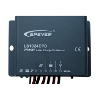
LS-EPD Series Solar Charge Controller
1. General Information
LS-EPD series solar charge controller adopts the most advanced digital technique and
operates fully automatically. It is ideal for extreme environments with corrosion, dust, water
etc and has various unique functions:
Electronic protection: Over charging, over discharging, overload, short circuit and reverse
protection of solar module
High efficient Series PWM charging, increase the battery lifetime and improve the solar
system performance
Widely used, automatically recognize day/night
Battery LED indicate battery status
Industrial design, wide application range
Digital tube menu, only one key solve all setting simply
Intelligent timer function with 1~13 hours option
IP67 protection
2. Features and Mounting
Charging Status LED indicator
Battery Status LED indicator
Mounting
1) Connect components to the charge controller in the sequence as shown above picture
and pay much attention to the “+” and “-”. Always power the battery firstly.
2) After power the battery, check the battery indicator on the controller, it will be green. If it’s
not green, please refer to chapter 4.
3) The battery fuse should be installed as close to battery as possible. The suggested
distance is within 150mm.
3. Indicators Description and Operation
1) Indicator Status Description
Charging Status
LED indicator
Battery Status LED
indicator
Radix Point of Digital
tube
(Load indicator)
2) Operation
The digital tube display the load work mode, please refer to the
correspondence table of Load Work Mode & LED digital tube value.
Pressing the key to configure the parameter, please refer to the
below configuration method:
1) After Powering on, disconnect the PV or connect the PV(Voltage<5V) , the light of the
digital tube point go on; Connect the PV(Voltage>6V) ,the light of the digital tube point
go off.
2)The key can be used to operate switching on/off the load (Manual control) or clearing
the faults
3) Keeping pressing the button over 5S, It will go to the parameter in browsing mode
which can cycle through the parameter item by clicking the button ,after the light of the
digital tube point going on.
4) After the digital tube displaying the value what you want to configure, releasing the key
and waiting 15S, Digital Tube stop flashing, then the configuration is successful.