12
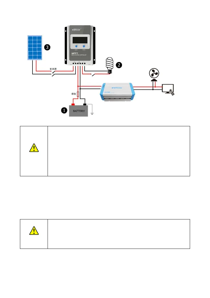
Figure 2-2 Wiring Diagram
Please do not close the circuit breaker or fuse during the wiring and ensure
that the leads of "+" and "-" poles are polarity correctly.
A fuse whose current is 1.25 to 2 times the controller's rated current must be
installed on the battery side with a distance from the battery no longer than
150 mm.
If an inverter is to be connected to the system, connect the inverter directly to
the battery, not to the load side of the controller.
Step 3:Grounding
Tracer-AN series are common-negative controllers. Negative terminals of the PV array, the battery, and
the load can be grounded simultaneously, or any negative terminal is grounded. However, according to
the practical application, the negative terminals of the PV array, battery, and load can also be
ungrounded. However, the grounding terminal on its shell must be grounded. It shields electromagnetic
interference and avoids electric shock to the human body.
For common-negative systems, such as the RV system, it is recommended to use a
common-negative controller. If a common-positive controller is used and the
positive electrode is grounded in the common-negative system, the controller may
be damaged.
Step 4:Connect accessories
Connect the temperature sensor
 Loading...