13
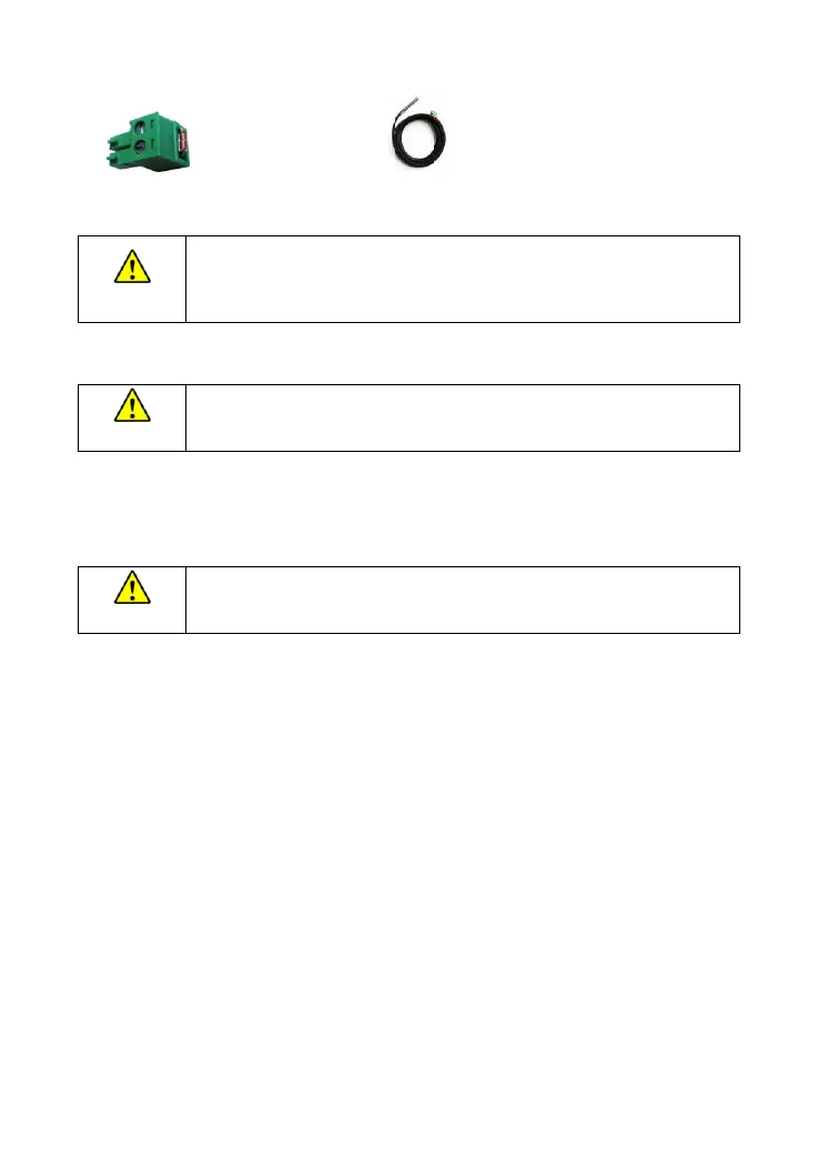
(Model: RT-MF58R47K3.81A) (Model: RTS300R47K3.81A)
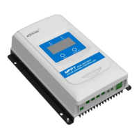
Connect one end of the remote temperature sensor cable to the interface ③ and place the other end
close to the battery.
Suppose the remote temperature sensor is not connected to the controller or
damaged. In that case, the controller will charge or discharge the battery at the
default 25 ºC (no temperature compensation).
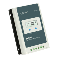
Connect the accessories for RS485 communication
Refer to 3.3 "Setting."
The internal circuit of the RS485 port has no isolation design. It is recommended to
connect an RS485 communication isolator to the port before communicating.
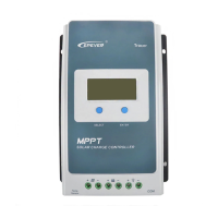
Step 5:Power on the controller
Closing the battery fuse will power on the controller. Check the battery indicator status (the controller is
operating normally when the indicator is lit green). Close the fuse and circuit breaker of the load and PV
array. Then the system will be operating in the preprogrammed mode.
If the controller is not operating properly or the battery indicator shows an
abnormality, please refer to 4.2 "Troubleshooting."
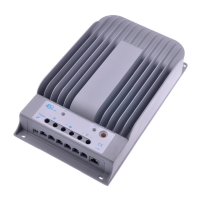
Included Accessory:
External temperature sensor
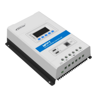
Optional Accessory:
Remote Temperature Sensor
 Loading...