Copyright
©
2021 SolarV GmbH All rights reserved
CAUTION: If the controller is to be installed in an enclosed box, it is important to ensure reliable
heat dissipation through the box.
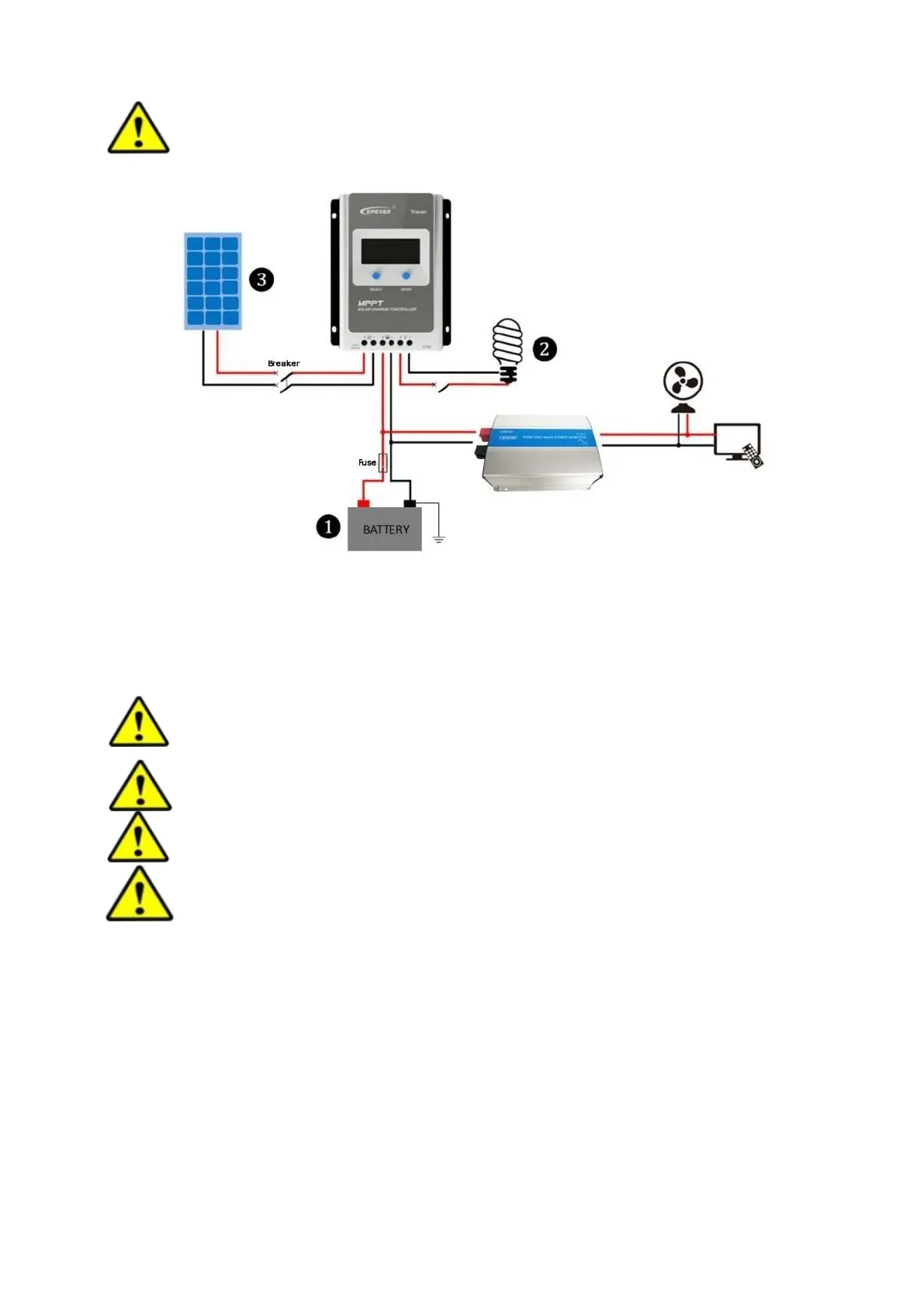
Figure 2-2 Schematic of wiring diagram
Step 2 : Connect the system in the order of ❶battery ❷ load ❸PV array in accordance with Figure
2-2,”Schematic Wiring Diagram” and disconnect the system in the reverse order❸❷❶.
CAUTION: While wiring the controller do not close the circuit breaker or fuse and make sure
that the leads of "+" and "-" poles are connected correctly.
CAUTION: A fuse which current is 1.25 to 2 times the rated current of the controller, must
be installed on the battery side with a distance from the battery not greater than 150 mm.
CAUTION: If the controller is to be used in an area with frequent lightning strikes or unattended
area, it must install an external surge arrester.
CAUTION: If an inverter is to be connected to the system, connect the inverter directly to
the battery, not to the load side of the controller.
Step 3:Grounding
Tracer AN series is a common-negative controller, where all the negative terminals of PV array, battery and
load can be grounded simultaneously or any one of them will be grounded. However, according to the
practical application, all the negative terminals

 Loading...