pg.4
101 2 3 4 5 6 7 8 9
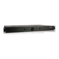
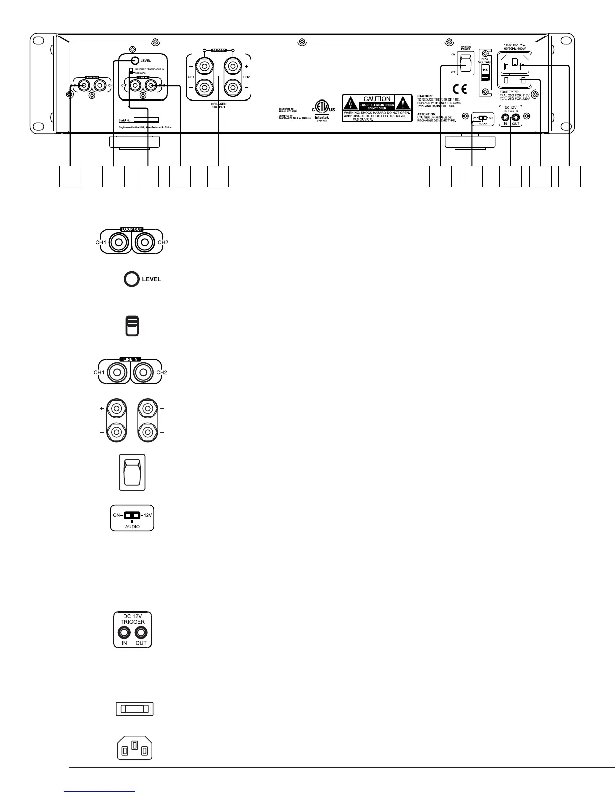
1. LOOP OUT
Allows Line In inputs to be sent to other ampliers
2. LEVEL
Master Gain Control for the amplier
3. BRIDGED SWITCH
Easily couple both channels together for increased power
NOTE: Maintain an 8 ohm minimum when using bridge mode.
4. LINE INPUT
Individual channel inputs
5. SPEAKER OUTPUTS
6. MASTER POWER SWITCH
Disables power to the amplier
7. POWER MODE SWITCH
Sets the ampliers power mode:
On – Turns ON / OFF via front power button
12V – Turns on when +12V is received at Trigger input
AUDIO - Turns on when a minimal amount of audio signal is received at the audio inputs and will
go into standby after 18 minutes of no audio signal.
Note: The front panel power button is inoperative when the 12V Trigger or Audio Sense power modes are
selected.
8. 12V TRIGGER IN/OUT
Turns amplier ON when 12V DC is applied and Power Mode Switch is set to 12V. This 12V signal is
regenerated to the 12V out for triggering additional ampliers.
Note: The front panel power button is inoperative when the 12V Trigger or Audio Sense power modes are
selected.
9. FUSE LOCATION
10. POWER CONNECTOR
REAR PANEL FEATURES