© 2012 Episode
pg.7
INSTALLATION – SETUP AND OPTIONS
POWER CONNECTION
Plug the supplied power cord into the amplier and to a polarized wall outlet or appropriate surge protector.
CAUTION: DO NOT plug the amplier’s power cord into a switched outlet, as is featured on some Surround Receivers. If you
wish to have the amplier turn on when the Receiver is powered up, use the 12V trigger jack or Audio Sense mode.
BRIDGING CHANNELS
There are situations when you may wish to combine two channels into one, or “bridging”. The output of the two combined channels
can then be used to power one speaker.
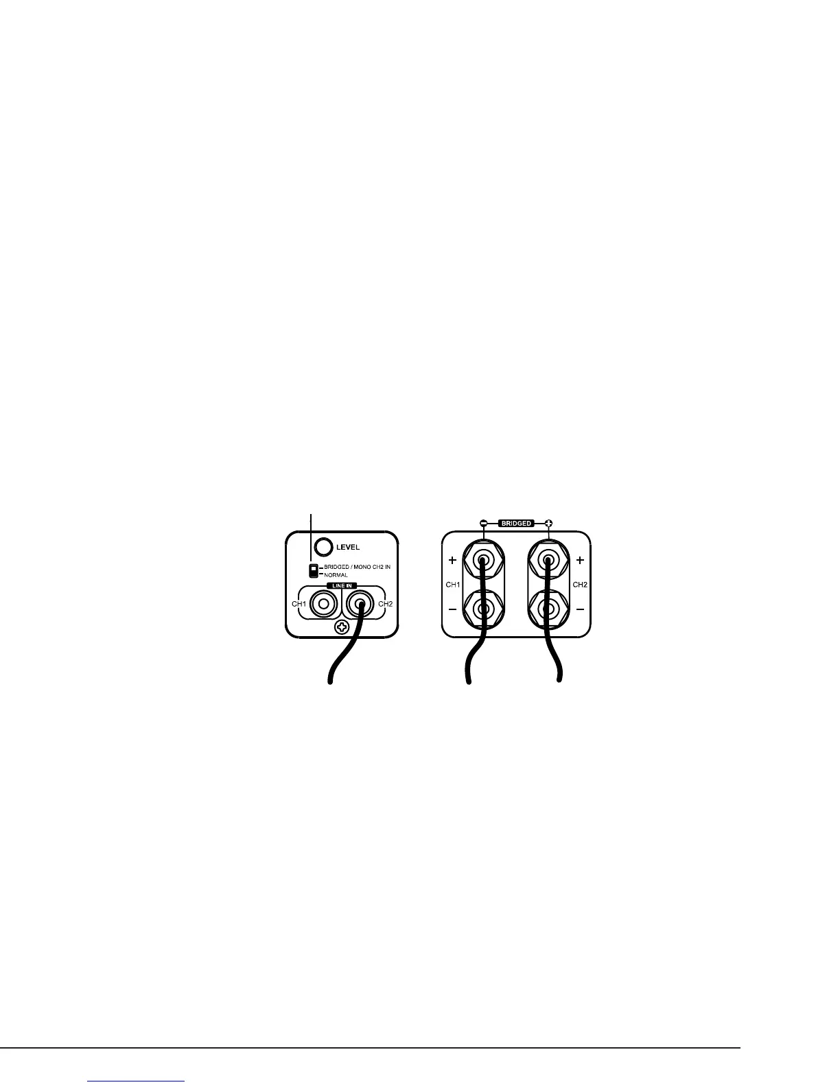
To Bridge Two Adjacent Channels:
1. Remove Power from the amplier.
2. Set the channel switch to BRIDGED/MONO.
3. Connect the (+) POSITIVE (RED) lead of the speaker to the (+)POSITIVE (RED) connection of the EVEN numbered channel.
4. Connect the (-) NEGATIVE (BLACK) lead of the speaker to the (+) POSITIVE (RED) connection of the ODD numbered channel.
5. Connect the output from the source to the LINE IN of the EVEN numbered channel.
Note:
• DO NOT connect more than one speaker to the outputs of the bridged channel.
• All input selection and volume settings for bridged channels will be controlled by the RED channel.
• Maintain an 8 ohm minimum when using bridge mode.
OPERATION
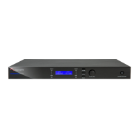
POWER SWITCH/ LED
The Power switch on the front panel of the amplier will turn off the amplier when the Power Mode Switch is set to ON.
BLUE – Amplier is ON
RED – Amplier is in STANDBY
Refer to the “Power Mode” section for further information.
ZONE LED INDICATORS
When lit, the LEDs on the front panel indicate the ampliers operating state. Each channel has one bi-color LED, for each zone.
BLUE – Amplier is ON and functioning properly
RED – Amplier is ON and is not functioning properly, check for possible short at Speaker Output
OFF – (When Power LED is BLUE) a channel is not functioning and may require service
LEVEL ADJUSTMENT
The level adjustment on the back panel of the amplier can be used to easily adjust the level of the amplier.
One great use for this feature is to limit the volume level. Be sure to set the volume at a level that does not clip or cause distortion
when the volume is at the maximum level. This can cause damage to the speakers and the amplier.
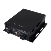
Switch in bridged mode
Speaker
(+) Positive
Speaker
(-) Negative
Source Output
 Loading...