U Page 45
Digital controller RK 4004
.8.2. usage input X 4.1
.8.3. usage input X 4.4
.8.4. usage input X 4.7
.8.5. usage input X20.2
.8.6. usage input X 3.2
The digital inputs (see wiring diagram) may be assigned functions.
Each function may only be assigned once.
The following table illustrates the possible function options:
Value Application Signal at active input
0 no usage no function of this input
1 Motor lock motor is stopped in each operating mode
-1 Motor unlock motor is enabled in each operating mode
2 Automatic lock motor is only stopped in automatic mode
-2 Automatik unlock motor is only enabled in automatic mode
3 Reference with speed- reference switch switches at negative motor direction of rotation (see example 1)
-3 Reference with speed+ reference switch switches at positive motor direction of rotation (see example 1)
4 Speed ± lock at signal 1 the motor direction of rotation is blocked. Which direction of rotation is inhi-
bited is only determined in conjunction with the reference switch. (see example 1)
-4 Speed ± unlock at signal 0 the motor direction of rotation is blocked. Which direction of rotation is inhi-
bited is only determined in conjunction with the reference switch. (see example 1)
5 Speed + lock at signal 1 the positive motor direction of rotation is stopped (see example 2)
-5 Speed + unlock at signal 0 the positive motor direction of rotation is stopped (see example 2)
6 Speed - lock at signal 1 the negative motor direction of rotation is stopped (see example 2)
-6 Speed - unlock at signal 0 the negative motor direction of rotation is stopped (see example 2)
7 Auto <-> Center switching-over between automatic and centering
-7 Center <-> Auto switching-over between centering and automatic
8 Oscillation ON oscillation ON
-8 Oscillation Off oscillation OFF
9 Weboffset Remote external web offset RE 1721 (only possible on terminal X 3.2!)
9- - not assigned
10 Webspeed Measure web speed measuring (only possible on terminal X 3.2!)
-10 - not assigned
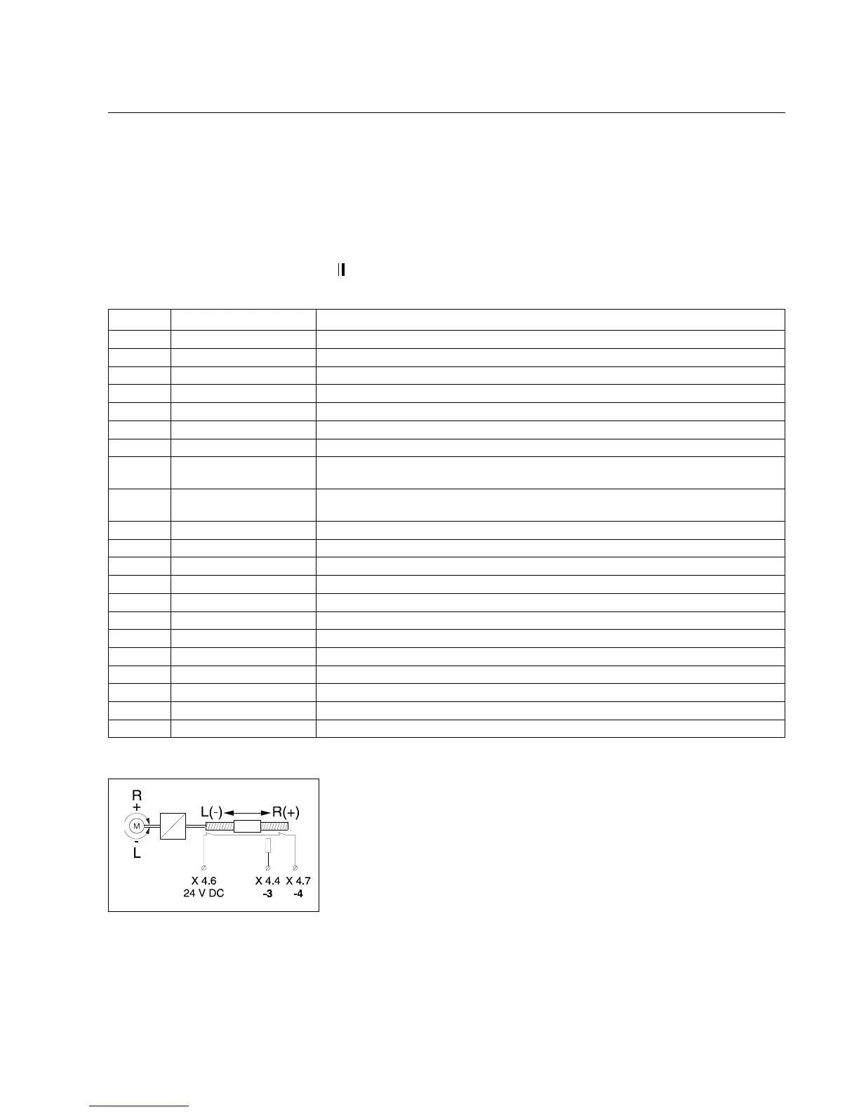
Example 1:
The positioning range is to be limited by two series-connected break
contacts.
The inputs X 4.4 (reference switch) and X 4.7 (end positions) should
be assigned as follows:
Input X 4.4 is assigned the value -3. The switching point is reached
via the positive
motor direction of rotation
.
Input X 4.7 is assigned the value -4 (break contact).