False alarms from detectors used for industrial applications can cost productivity in down time. This is especially noted for
automated systems and processes.
Conversely, failure to generate an alarm can have catastrophic results.
The combination of microprocessor, algorithms, multiple sensors and wavelength range settings makes the IPES‐IR3 an
excellent choice for elimination of false positive indicators caused by non‐flame sources of radiation such as artificial
lighting, direct and indirect sunlight, lightning, electrical arcs, radiation (nuclear), arc welding and metal grinding.
An Alarm condition will normally override a Fault condition unless a loss of operating power impairs the detector’s ability to
generate or maintain an alarm. The IPES‐IR3 reports both Fault and Alarm conditions exclusive of each other. This means
both a Fire and Fault can be reported at the same time if they occur simultaneously.
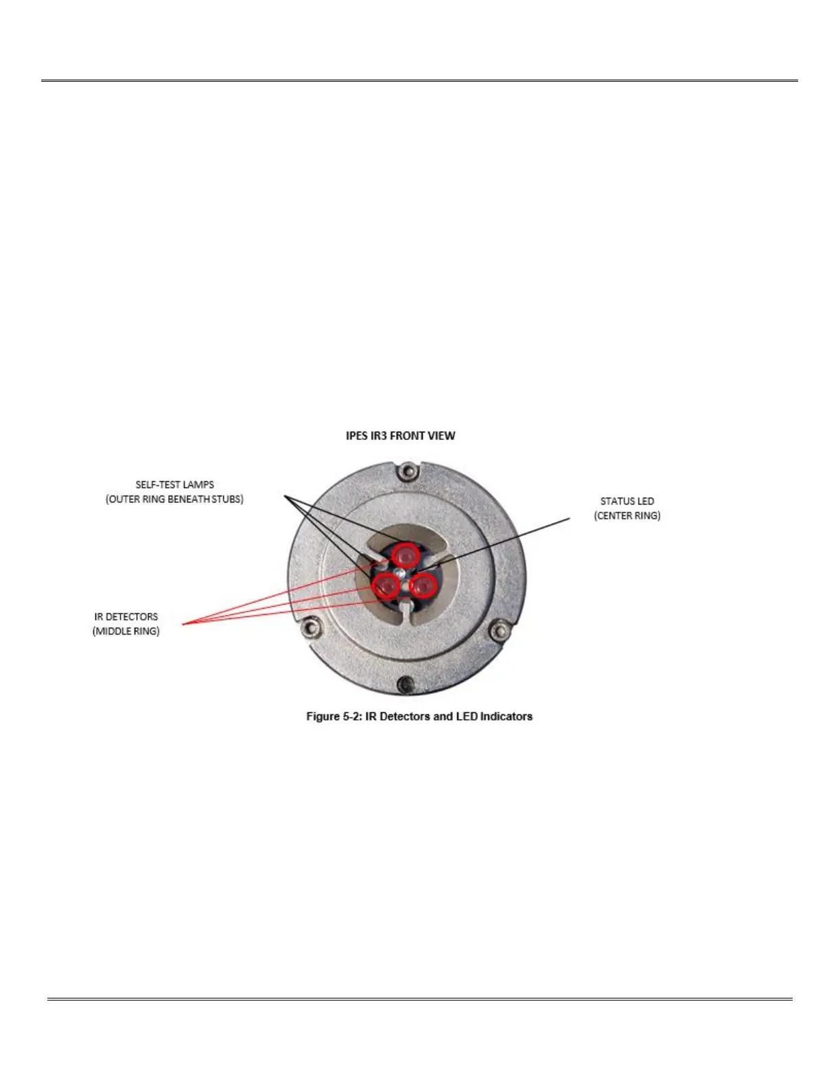
To maintain reliability of the IPES‐IR3, the optical devices are automatically self‐tested for
radiation transmission
every 25 to 45 minutes. This routine test does not require the use of a test lamp. This test determines whether any
dust or other contamination has formed on the detecting windows which would scatter the infrared radiation.