Arrangement of
Electrical Connections
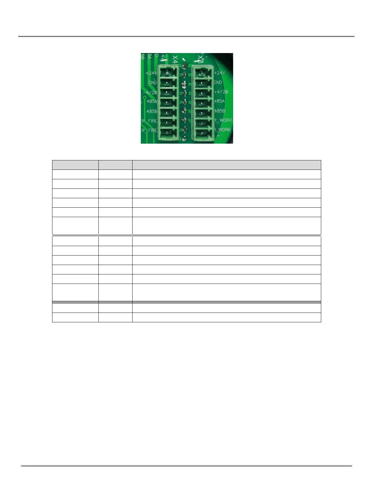
Arrange the electrical connections as described in Table 6‐1, Table 6‐2 and Figure 6‐3 below.
To connect the IPES‐IR3 to external devices, use armored control cables 4 x 1.5, which are used in
all classes of explosive zones including indoor and outdoor sites, channels, tunnels, ground
(trenches) with corrosive medium, and in zones containing roaming currents.
Setting the Modbus
Address and Baud Rate
To ensure proper communications, a unique address must be assigned to each device, as duplicate
addresses are not automatically detected. Modules with duplicate addresses will report with the
same address, confusing latest updates. Record all addresses and device types after completing the
installation.
Refer to Appendix B for setting the Modbus address and baud rate.
When using an RS‐485 bus connection, it is advisable to connect the IPES‐IR3 to the bus via the
terminal box. To connect the detector to the terminal box, use a cable not longer than
1.64
feet (0.5 m). The cable characteristics should meet the requirement of the cable entries
mounted on the IPES‐IR3 casing and those of the terminal box.