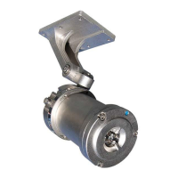
The IPES‐IR3 detector component parts and delivery set consists of the following:
• One IPES‐IR3 Fire Detector
• One Adjustable Mounting Bracket
• One Operating Manual
• IPES Mounting Hardware (bolts, nuts, washers, etc.).
• One Sunshade Hood
• Optional magnetic collar (delivered only by special request).
Compare the contents of the set to the packing list to be sure all items were received. If any items are missing, contact
ESP Safety Inc.
• The nameplates and warning labels are in place.
• The external surfaces of the elements and joined surfaces of the casing are free of dents or damage.
• The tamper‐proof screw is intact on the front cover
Positioning the Detector
1. Position the detector to provide an unobstructed view of the area to be protected. The detector’s 90° viewing angle
is most sensitive along the central axis; therefore, position the central axis so that it has the best unobstructed view
of the place of probable fire. Use line of sight or laser level for more precise targeting.
2. Identify all high-risk fire sources, to determine the number of detectors needed for adequate coverage.
3. Locate the detector(s) for ease of cleaning and servicing. Ensure that probable fire sources are within the
detector(s) field of view and detection range.
4. When installing multiple detectors in the same area, be aware of overlapping fields of view and detector hierarchy.
Overlapping fields of view can be used to provide additional protection against false positives or false negatives,
depending on the control system logic connected to the detectors.
Note: To mitigate false positives, position the detector so that its field of view does not cover any areas outside the
hazardous area.
5. Mount the detector on a rigid surface which minimizes vibrations. Use the mounting hardware provided along with
the rubber bushings to further isolate the detector from vibrations
Note: ESP Safety Inc. recommends bolting the mounting base plate to the mounting surface. If bolting is not
possible, the mounting plate can be welded to the mounting surface if it is a similar metal (either 316 Stainless Steel
or 6061 aluminum). Before welding, be sure to remove the detector from the base plate before attempting any
weld operation.
Warning: Do not open, separate or disassemble casing when
energized! Separating the casing can result in serious damage to
the detector which could go undetected, resulting in failure to
detect fires.