Page 20 of 37
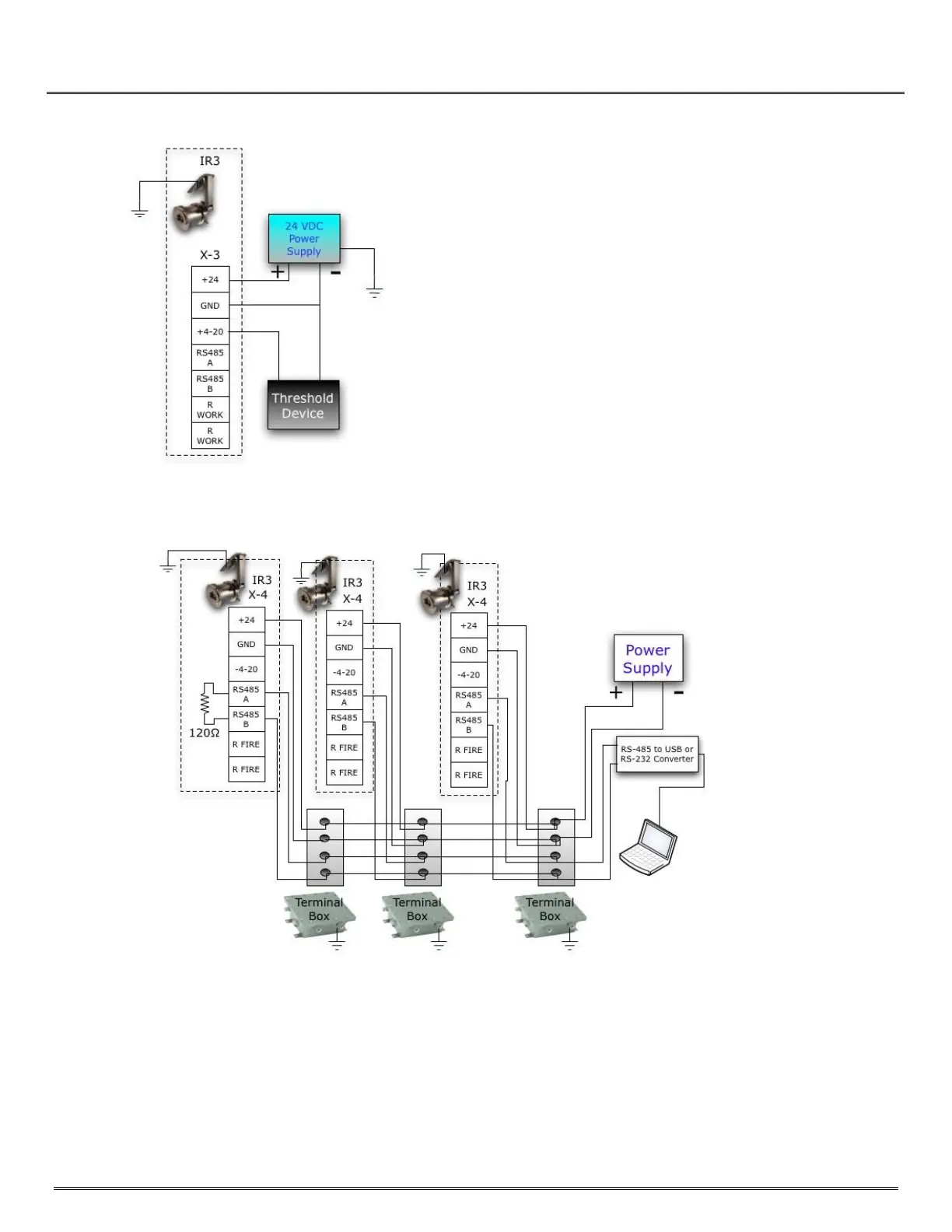
IPES‐IR3 3 Wire +4 to 20 mA Current Loop Wiring Diagram
When using the current loop method of connection the circuit is a point‐ to‐point
connection between a single IPES‐IR3 and a threshold detection device. In most cases the
threshold device will provide the 24VDC power and will operate in a closed loop. Refer to
Appendix C for interpretation of
+4 to 20ma indications.
If 24VDC is from a common source, use of a connection bus‐block is recommended
to provide connect/disconnect capability without disruption to any other devices
using the same power source.
Figure 6-3: IPES-IR3 Connection to Analog +4 to 20 mA Current Loop
Connection to Digital RS‐485 Circuit
Figure 6-4: IPES-IR3 Connection to Digital RS-485 Circuit