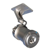
After a successful test, the output signals of the IPES‐IR3 will be in the following states:
• Actuation (closure of contacts) of ‘Fault relay, indicating a ‘Working order’/operational condition.
• Indicator led has a solid green light, which corresponds to the ‘Normal work’/operational mode of the detector
as detailed in the next image.
• The +4‐20mA analog output will be at (4±0,1) mA (Operational Status)
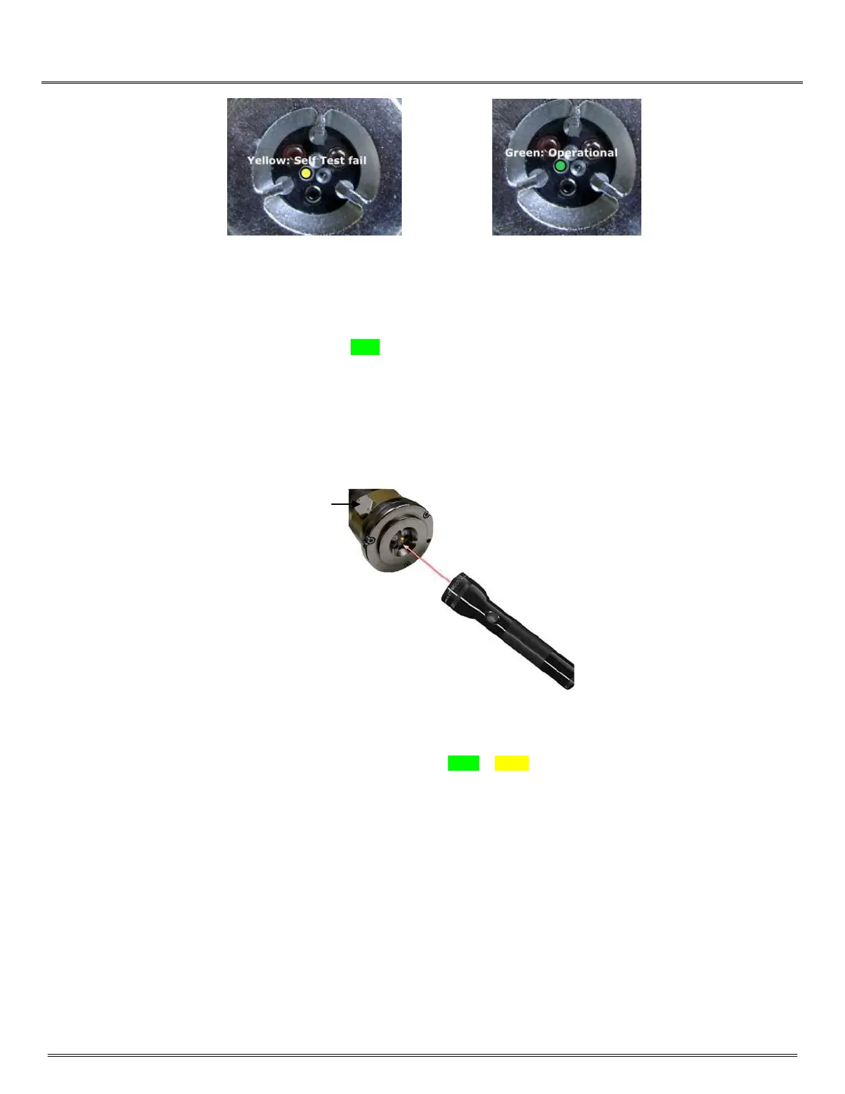
After installation is complete, conduct a fire detection test to ensure that the detector properly detects a fire condition.
An optional Test Lamp in conjunction with a magnetic Test collar are used to perform the test on the IPES‐IR3.
Fig 7-1: Placement of Magnetic Collar and Testing with Test Lamp
• Attach the Magnetic Collar with the Magnet placed into the slot on the enclosure. This will put the IPES‐IR3 into
Fault Mode and the status LED will change from Green to Yellow indicating a Test function.
• Point the laser beam at the mid‐range sensor 4.45 uM IR detector. This will set the IPES‐IR3 into fire indication
mode. The status indicator will now blink yellow‐red indicating both Fault and Fire conditions.
• To prevent a false alarm during this test, the Fault relay will be actuated (In an open state) and the Fire relay will
remain in a not active state (Open)
• The Analog +4 to 20mA will indicate 2mA for Test Mode
• Once testing is successfully completed, remove magnetic collar to return the IPES‐IR3 into operation.