Page 14
the module’s Vmp. In a 12V system for example, the battery voltage may range from
11-15Vdc but the module’s Vmp is typically around 16 or 17V.
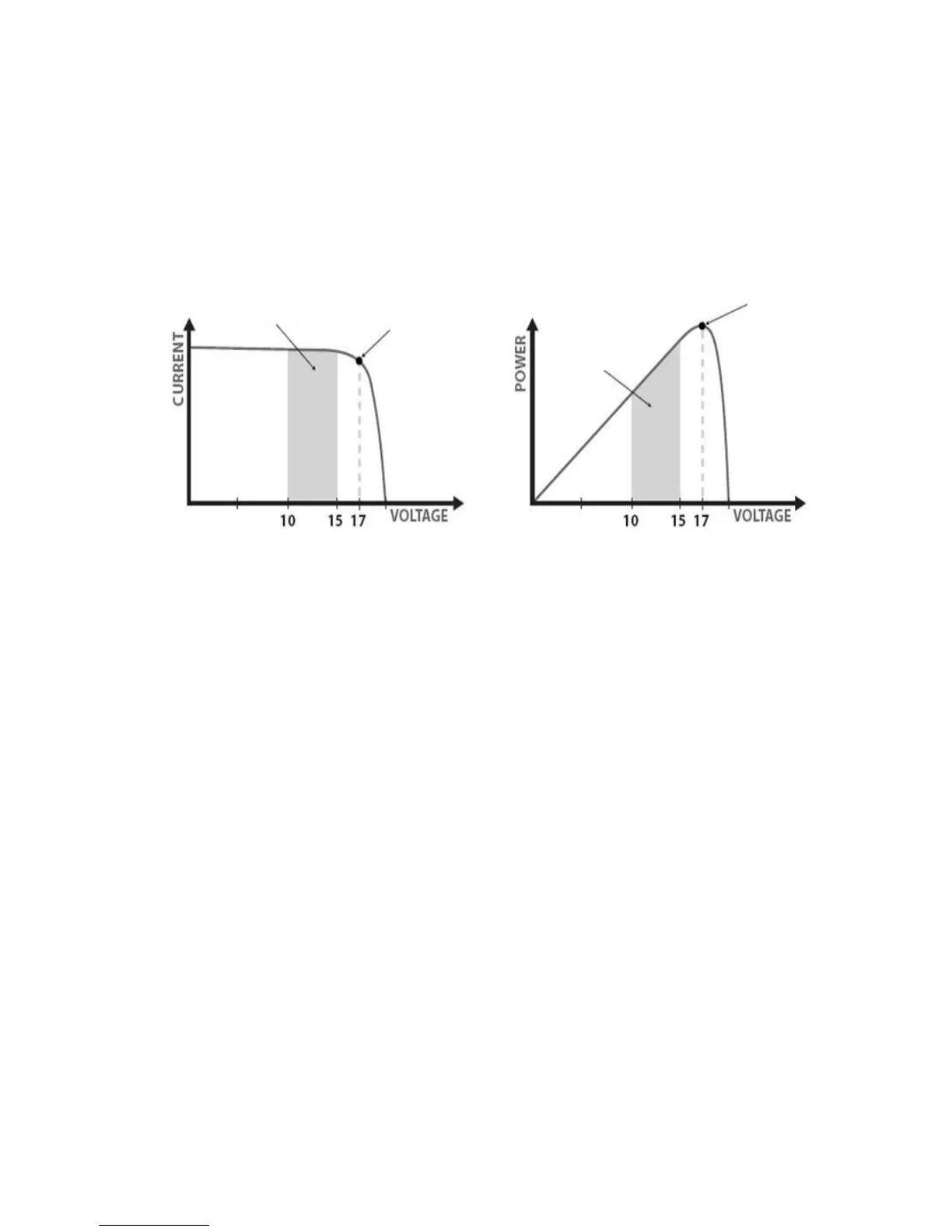
Figure 4-1 shows a typical current VS. voltage output curve for a nominal 12V
off-grid module.
Current VS. Voltage in 12V system Output power in 12V system
Figure 4-1 Nominal 12V solar module I-V curve and output power graph
The array Vmp is the voltage where the product of current and voltage (Amps×Volts)
is greatest, which falls on the ‘knee’ of the solar module I-V curve as shown in
Figure4-1. Because Traditional controllers do not operate at the Vmp of the solar
modules(s), energy is wasted that could otherwise be used to charge the battery and
power system loads. The greater the difference between battery voltage and the Vmp
of the module, the more energy is wasted.
eTracer MPPT technology will always operate at the Vmp resulting in less wasted
energy compared to traditional controllers.
·Conditions That Limits the Effectiveness of MPPT
The Vmp of a solar module decreases as the temperature of the module increases. In
very hot weather, the Vmp may be close or even less than battery voltage. In this
situation, there will be very little or no MPPT gain compared to traditional controllers.
However, systems with modules of higher nominal voltage than the battery bank will
always have an array Vmp greater than battery voltage. Additionally, the savings in
wiring due to reduced solar current make MPPT worthwhile even in hot climates.