Page 5
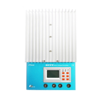
1 –LCD
Display interface, 128x64 dot-matrixes
2 –Buttons
Browse or modify all parameters.
3 – Battery Indicator
An LED indicator shows battery status.
4 – Charging Indicator
An LED indicator shows charging or not.
5 – Faults Indicator
An LED indicator shows controller faults.
6 –Terminal
Refer to Figure 2-2
7 – Serial RS-232 Port (DB9)
Monitor controller by PC or update controller software.
8 – Ethernet Port (RJ45)
Connect Ethernet, monitor controller remotely by network.
9 – Solar polarity reversed Indicator
An LED indicator shows solar modules positive and negative reversed.
10 – Remote Temperature Sensor Port (MC1.5-3.81-2L)
Connect RTS, Measure battery temperature to make temperature compensation.
11 – Remote Battery Voltage Sensor Port (MC1.5-3.81-2L)
Connect RBVS, measure battery voltage accurately.
12 – CAN BUS Port (MC1.5-3.81-4L)
Communicate with other CAN BUS devices made by EPsolar.