Appendix
Rev. A
A-2
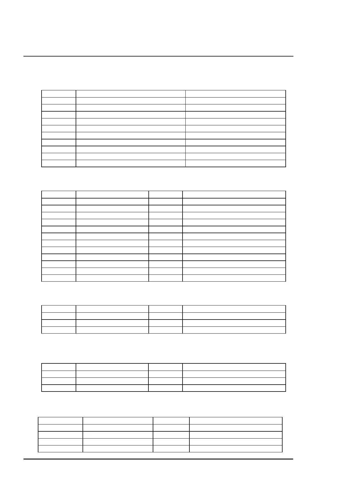
A.2 Connector Summary
Following tables show connector pin assignment of the C200 main board.
Connector Function Table to refer
CN1 Parallel I/F connector Chapter1/Table 1-10
CN2 Serial I/F connector Chapter1
CN3 •ËControl panel Table A-2
CN4 •ËPE sensor Table A-3
CN5 •ËHP sensor Table A-4
CN6 •ËCR motor Table A-5
CN7 •ËPF motor Table A-6
CN8 •ËPrint head Table A-7
CN10 •ËPower supply board (C206 PSB) Table A-8
CN11 •ËASF sensor Table A-9
Pin Signal Name I/O Function
1 LED0 Out LED drive signal (0)
2 GND ---- Ground
3 LED1 Out LED drive signal (1)
4 GND ---- Ground
5 LED2 Out LED drive signal (2)
6 +5V ---- Logic power supply
7 +5V ---- Logic power supply
8 LED4 Out LED drive signal (4)
9 SW1 In Panel switch input (1)
10 PSC In Power on/off switch
11 SW0 In Panel switch on/off (0)
12 SW2 In Panel switch on/off (2)
Pin Signal Name I/O Function
1 PE In Sensor detect signal
2 GND --- Ground
3 PEV --- Sensor power supply(+5V)
Pin Signal Name I/O Function
1 HP In Sensor detect signal
2 GND --- Ground
3 HPV --- Sensor power supply(+5V)
Pin Signal Name I/O Function
1 CRA Out Phase drive signal(A)
2 CR-A Out Phase drive signal (-A)
3 CRB Out Phase drive signal (B)
4 CR-B Out Phase drive signal(-B)
Table A-1. Connector summary of the C206 Main board
Table A-2. Connector CN3
Table A-3. Connector CN4
Table A-4. Connector CN5
Table A-5. Connector CN6