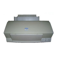
EPSON Stylus Color 600
Rev. A
2-1
2.2 Electrical Circuit Operating Principles
Stylus Color 600 contains the following four electric circuit boards.
C206 PSB/PSE board
C200 Main board
Head Driver board
C206 PNL board
C206 PSB/PSE, C200 board are explained in this section. The head drive board is installed in the head
uniton the carriage. The figure below shows major connection of the 3 boards and their roles.
PF MOTOR
(Pump Motor)
CR Motor
+5 V DC
+42 V DC
AC100V
INK END Sensor
(Firm Wear)
PE Sensor
BCO/CCO Sensor
ASF Lever
Position Sensor
Print Head
Head Drive Board
Thermistor
+5 V DC
+42 V DC
Main Control Board
(C200 Main Board)
RCC Switching Regulator
(C206 PSB/PSE Board)
Figure 2-17. Electric Circuit of Stylus Color 600