Chapter2 Operating Principles
Rev. A
2-
2.1.1.1.1 Printing Process
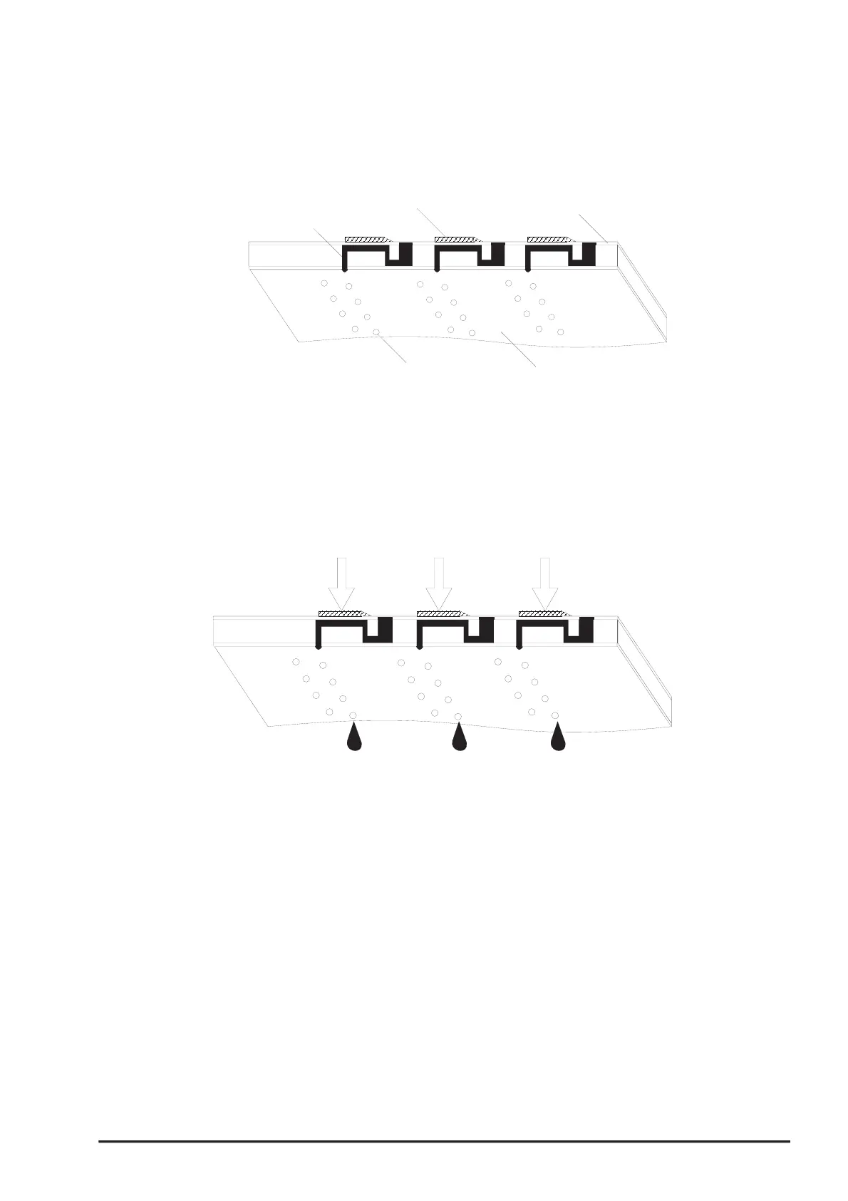
Following figures indicate the sectional drawing of normal state and ejecting state of print head.
(1) Normal State:
When the print signal is not output, PTZ also does not move in the waiting state(normal state).
(2) Ejecting State:
When the print signal is output from the C200 main board, IC(IR2C72C and IR2C73C:Nozzle
Selector) located on the print head unit latches the data once by 1-byte unit. Appropriate PZT latched
by nozzle selector is pushed in to the cavity by applying common voltage from the C200 main
board. By this operation, ink that is stored in the cavity pops out from nozzles.
Nozzle
Nozzle Plate
PZT
Ink Course
Cavity
Figure 2-3. Print Head Normal State
Figure 2-4. Print Head Ejecting State