The following tables show the signal names that are present at the parallel and serial
sockets on your printer.
If you are having trouble selecting a cable that will work with your computer:
❐ Show these tables to your computer hardware dealer.
❐ Check the pin assignments of your computer’s printer port (parallel or serial, depend -
ing which one you are having problems with), and show that to your hardware
dealer as well.
In most circumstances, a normal cable will work.
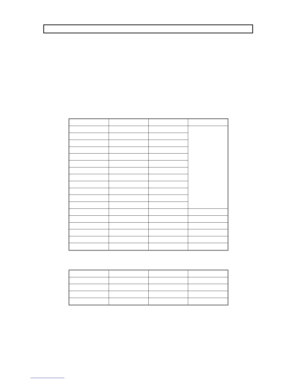
Parallel Interface
Pin Number Signal Name Pin Number Signal Name
1 STROBE 19
GND
2 DATA1 20
3 DATA2 21
4 DATA3 22
5 DATA4 23
6 DATA5 24
7 DATA6 25
8 DATA7 26
9 DATA8 27
10 ACKNLG 28
11 BUSY 29
12 PE 30
13 SLCTOUT 31 INIT
14 AUTOFEED 32 ERROR
15 -- 33 GND
16 GND 34 --
17 CHASSIS GND 35 +5V
18 -- 36 SLCTIN
Serial Interface
Pin Number Signal Name Pin Number Signal Name
1 FG 5 CTS
2 TXD 6 DSR
3 RXD 7 SG
4 RTS 20 DTR
APPENDIX F. CONNECTOR PIN CONFIGURATION
F-1