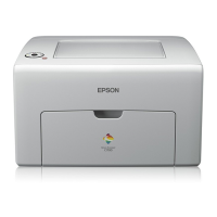
Epson AcuLaser CX-11N/AcuLaser CX-11NF Field Repair Guide 9/9/05
Printer Component, Software Item, LCD Display, Printer Button Page 28.
Fax Board (PPL Ref # 12-02-16)
Provides the interfacing and protocol handling between the unit, the Telco and distant end fax machine.
Network Board (PPL Ref # 12-02-09)
Provides the interfacing and protocol handling between the unit and an ethernet network.
Scanner Circuit Boards
The scanner mechanism is powered and controlled directly by the main controller (PWBA ESS). It does not have its
own control circuit.
The scanner power requirements are +24VDC (to drive the CR Motor and power the Inverter Circuit), +12VDC and
+5VDC (for the CCD Sensor), and +3.3VDC (for the Home Sensor and the Magnet Sensor). The control signals to
the scanner unit from the main controller are CCD Sensor drive control, CR Motor drive control, and ADF drive con-
trol.
CCD Sensor Board (PPL Ref # 18-01-14)
Contains a Color CCD line sensor and a control circuit for the Color CCD line sensor.
Inverter Board (PPL Ref # 18-01-27)
Generates the voltage for the scanner lamp.
ADF Circuit Boards
ADF PCB (PPL Ref # 13-01-08)
Generates motor drive and an interface between the ADF sensors and the PWBA ESS (Main Logic Board).
manuals4you.commanuals4you.com
 Loading...
