J
EPSON
PRINTERS
4.7
PRINTER
MECHANISM
Removal
3.
4.
Remove Upper Case(4.1).
Remove
the
connectors
from
the
Printer
Mechanism
to
the
Main
Circuit
Board
(refer
to
the
General
Section
6.4
-
Cable
Connectors)
Remove
the
screws
securing
the
printer
mechanism
to
the
printer
chassis
(refer
to
Parts
Lists
illustrations).
Lift
the
printer
mechanism
free
from
the
printer
base.
Replacement
1.
Reassemble
in
reverse
order.
4.8
PRINT
HEAD
UNIT
Refer
to
Figure
4-6
Removal
1.
Remove
Uppercase
(4.1).
2. Move
the
print
head
to
the
right
end
of
travel.
3.
Remove
the
head
cable
from
the
connector
on
the
terminal
board.
4.
Turn
the
head
lock
lever
clockwise
and
lift
the
print
head
unit
free
(fig. 4-6).
Replacement
1.
Reassemble
in
reverse
order.
2. Perform Print Head
Adjustment.
Htadlocklavar
CcrrfigaMMmtllv
Print
haad
Httd
ctbl*
Print
htid
unit
.•Tarmintl
Htad
connactoi
*Sa
tur*
to
hold
ihit
con-
ntcior
llrmly
(o pull
htad
e«bl0
out
tiraiohi.
Figure 4-6 Print Head Unit
4.8.1
PRINT
HEAD
Adjustment
Refer
to
Figure
4-7
1.
RemovetheUppercase(4.1).
2. Remove
the
print
head
(4.8).
3. Remove
the
ribbon
mask by removing
the
two
screws securing it
to
the
Carriage
(Tig.4-
7,
insert).
4. Reinstall
the
print
head
and
lock it m
?osition
without
the
ribbon
mask.
urn
the
rear
carriage
shaft
until
the
widest
portion of the hole in the left side of the
shaft
isup. Insert a thin screwdriver
through
the
hole
on
the
CarriageShaft.
6.
Using
the
screwdriver hold
the
shaft in
position and loosen the nut on the left end
of
the
shaft.
4-3
REPAIRS/ADJUSTMENTS
AOJUSTMIINTlEVEn
6.
7.
8.
1
tf
I
SlUt
VILW
RIBBON
MASK
HEAD
LOCK
LEVER
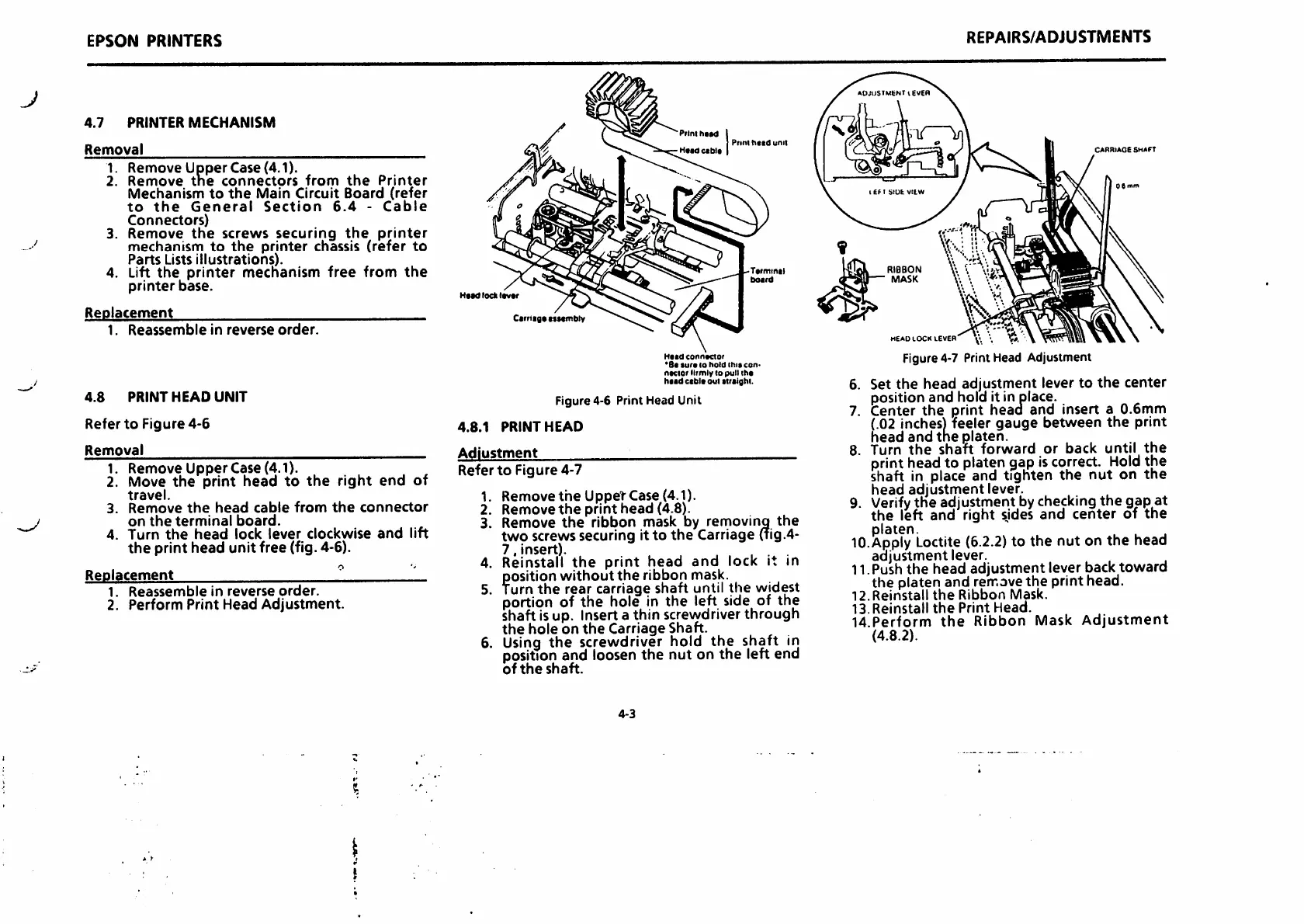
Figure 4-7 Print Head Adjustment
CARRIAGE
SHAFT
Set
the
head adjustment lever to
the
center
position and hold it in place.
Center
the
print head and insert a 0.6mm
(.02
inches)
feeler gauge between the print
head and
the
platen. .
Turn
the
shaft
forward
or
back
until
the
print head to platen gap iscorrect.
Hold
the
shaft in place and tighten
the
nut
on
the
head
adjustment
lever.
9. Verify
the
adjustment bychecking
the
gap
at
the
left and right sides and
center
of
the
platen.
...
10.Apply
Loctite
(6.2.2)
to the nut on the head
adjustment
lever.
11.Push
the
head
adjustment
lever back
toward
the
platen and remove
the
print head.
12.Reinstall
the
Ribbon
Mask.
13.
Reinstall
the
Print
Head.
U.Perform
the
Ribbon
Mask
Adjustment
(4.8.2).

 Loading...


