EPSON
PRINTERS
1.1
PRINCIPLES
OF
OPERATION
The
descriptions
of
the
printer
mechanics is
generic
to
all models
with
few
exceptions.
O
PRINTER
MECHANISM
Theprinter
mechanisms
are dot
matrix
mechanisms
withsub-miniature print
heads
developed
for
high
quality, precision
printing.
Because
some
the
units
come
with
tractor
feed
attachments
and
also
are
equipped
with
rubber
plates,they maybe usedwith continuousbusiness
forms
or rolledor cutsheet
paper, as required by
the
user. No special additional equipment need be
purchased
to
accommodate
the
various
paper
types. Basic
operation
of
all
the
models
is
essentially
the
same.
Sensor
Mechanisms
Sensor
mechanisms
on
all
models
include
the
home
position
(HP),
print
^
timing
(PTS),
and
the
paper
end
(PE)
sensors.
Home
Position
(HP)
Sensor
The
HP
sensor
assembly
consists
of
a HP
sensor
and
a
sensor
plate,
situated
beneath
the
carriage
assembly.
The
sensor
emits
a HIGH
signal
whenever
the
sensor
plate
intercepts
the
optical
axis
of
the
photo
sensor.
The
variations
in
the
signal
alert
the
main
CPU as
to
when
the
carriage
is in
or
out
of
the
home
position (i.e.
the
left
end
of
the
platen).
This signal serves as a
reference
signal for
the
printing
operation.
^
Print
Timing
Sensor
(PTS)
The
PTS
sensor
mechanism
consists
of
the
sensor
and
a
sensor
disk,
located on
the
shaft
of
the
carriage motor. The
PTS
signal is
generated
in
order
to
coordinate
carriage
speed
with
firing of
the
dot
wires,
allowing
adequate
time for
the
print
operation
to be performed. A
HIGH
signal
isemitted as the
slits
inthe
disk
pass
the
optical
axis
of the
photo
sensor.
1-1
PRINCIPLES
OF
OPERATION
Paper
End (PE)
Sensor
The
PE
sensor
consists
of
a
reed
switch
mounted
on
the
PE
sensor
board
and
a
reed
magnet
mounted
on
a PE
sensor
lever.
The
assembly is
attached
at
the
rear
of
the
printer
mechanism.
When
the
printer
runs
out
of paper,
the
reed
magnet
and
reed switch
meet
causing
the
PE
warning
signal
to
be
output.
PRINT
ASSEMBLY
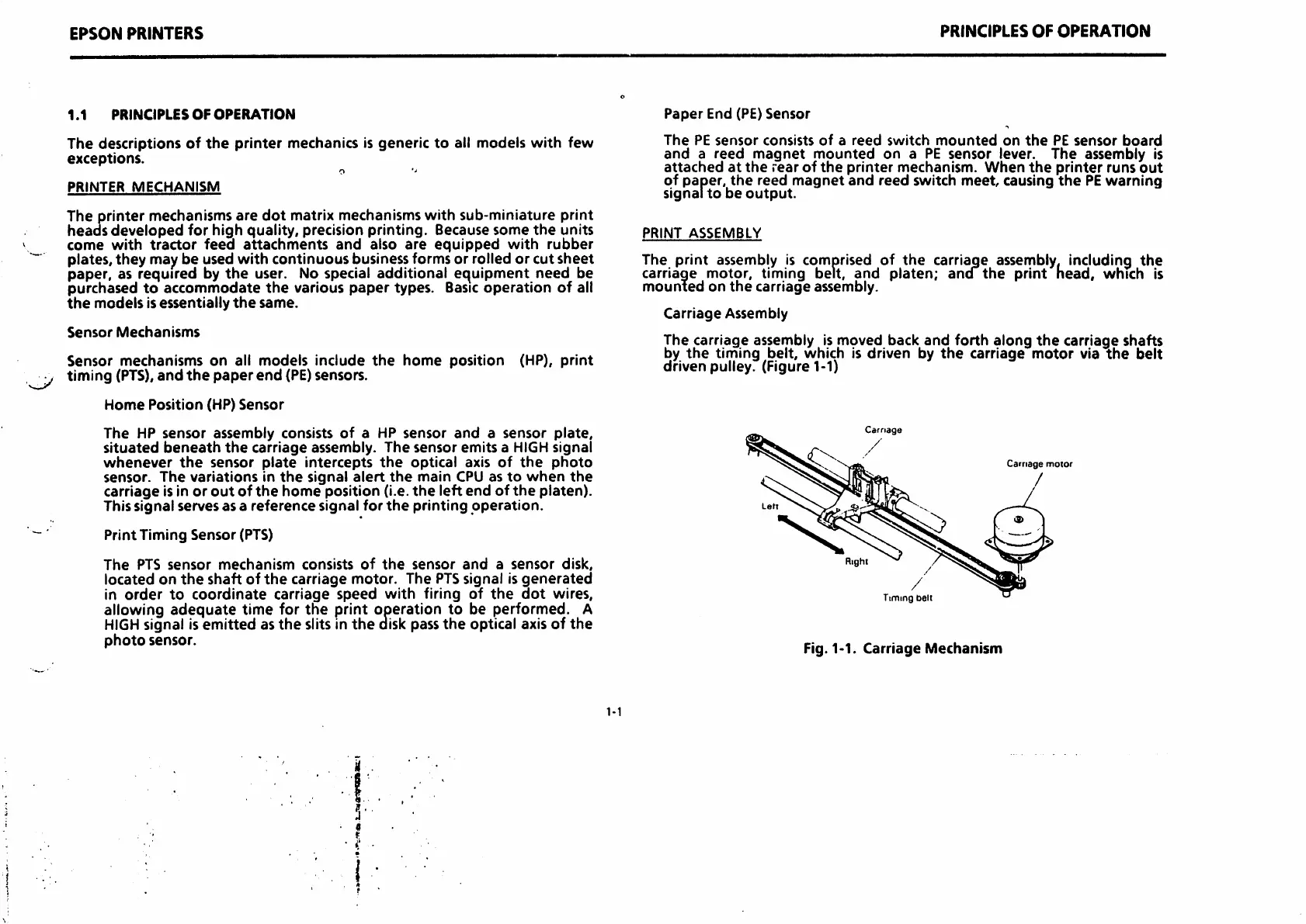
The print assembly is comprised of the carriage assembly, including the
carriage motor,
timing
belt, and platen; ancf the print head,
which
is
mounted
on
the
carriage
assembly.
Carriage
Assembly
The carriage assembly is moved back
and
forth
along
the
carriage shafts
by
the
timing
belt,
which
is
driven
by
the
carriage
motor
via
the
belt
driven pulley. (Figure 1-1)
Carnage
Carnage
motor
Timing
belt
Fig. 1-1.
Carriage
Mechanism

 Loading...


