EPSON
PRINTERS
Note:
1. If the host computer is not equipped with
the
power supply for
the
Current
Loop
interface, these jumpers must be
connectecT
to perform
communications
via
the
Current
Loop
interface.
2.
Either
J7A
or
J7B
must
be
connected.
Since
this
interface
board
is
factory-
set
to
use
the
8K
byte
RAM,J7A is
connected.
3. Either J9A
or
J9B
jumper
is
connected
at
the
factory,
and
this
setting
should NOTbe
changed
by
the
user. Check
the
setting
on
your
board
and
fill
in
the
table
for
future
reference.
4. Either JX
or
JF
jumper
must
be
connected.
5. Either JCL
or
JRS
jumper
must
be
connected.
Jumper
Settings
for
RS-232C
and
Current
Loop
Refer
to
Table
6-23
to
select
from
four
available
protocol
selections.
Table 6-23
Jumper
Settings
for
RS-232C
and
Current
Loop
J8A
ON
or
OFF
ON
ON
or
OFF
ON
J8B
ON
OFF
ON
OFF
JX
ON
ON
OFF
OFF
JF
OFF
OFF
ON
0
N
JRS
ON
OFF
ON
OFF
ON
OFF
ON
OFF
JCL
OFF
ON
OFF
ON
OFF
ON
OFF
ON
RS-232C
level
Current
Loop
XON/XOFF
control
0 X
X X 0 X
X
X
Flag
Control
0
X 0
X
0
X 0
X
XON/XOFF
control
X 0
X
0
X X
X
X
Flag
Control
X X
X
X X 0
X
0
O:
Protocol
possible
X:
Protocol
impossible
6-23
GENERAL
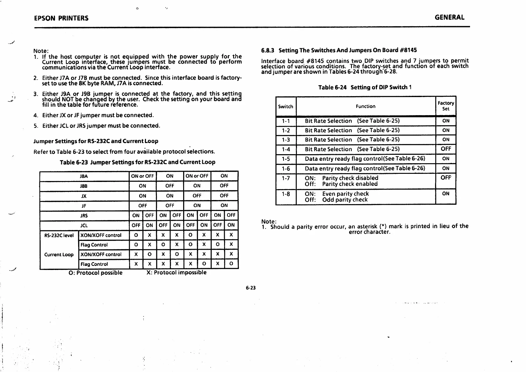
6.8.3 Setting The SwitchesAnd Jumpers On Board #8145
Interface
board
#8145
contains
two
DIP
switches
and
7 jumpers
to
permit
selection of various conditions. The factory-set
and
function of each switch
and
jumper
are
shown
in Tables
6-24through'6-28.
Table
6-24
Setting
of
DIP
Switch
1
Switch
Function
Factory
Set
1-1
Bit
Rate
Selection
(See
Table
6-25)
ON
1-2
Bit
Rate
Selection
(See
Table
6-25)
ON
1-3
Bit
Rate
Selection
(See
Table
6-25)
ON
1-4
Bit
Rate
Selection
(See
Table
6-25)
OFF
1-5
Data
entry
ready
flag control(See Table 6-26)
ON
1-6
Data
entry
ready
flag control(SeeTable 6-26)
ON
1-7
ON: Parity check
disabled
Off: Parity check
enabled
OFF
1-8
ON: Even parity check
Off:
Odd
parity
check
ON
Note;
1. Should a parity error occur, an asterisk (*) mark is printed in lieu of the
error
character.

 Loading...


