EPSON
PRINTERS
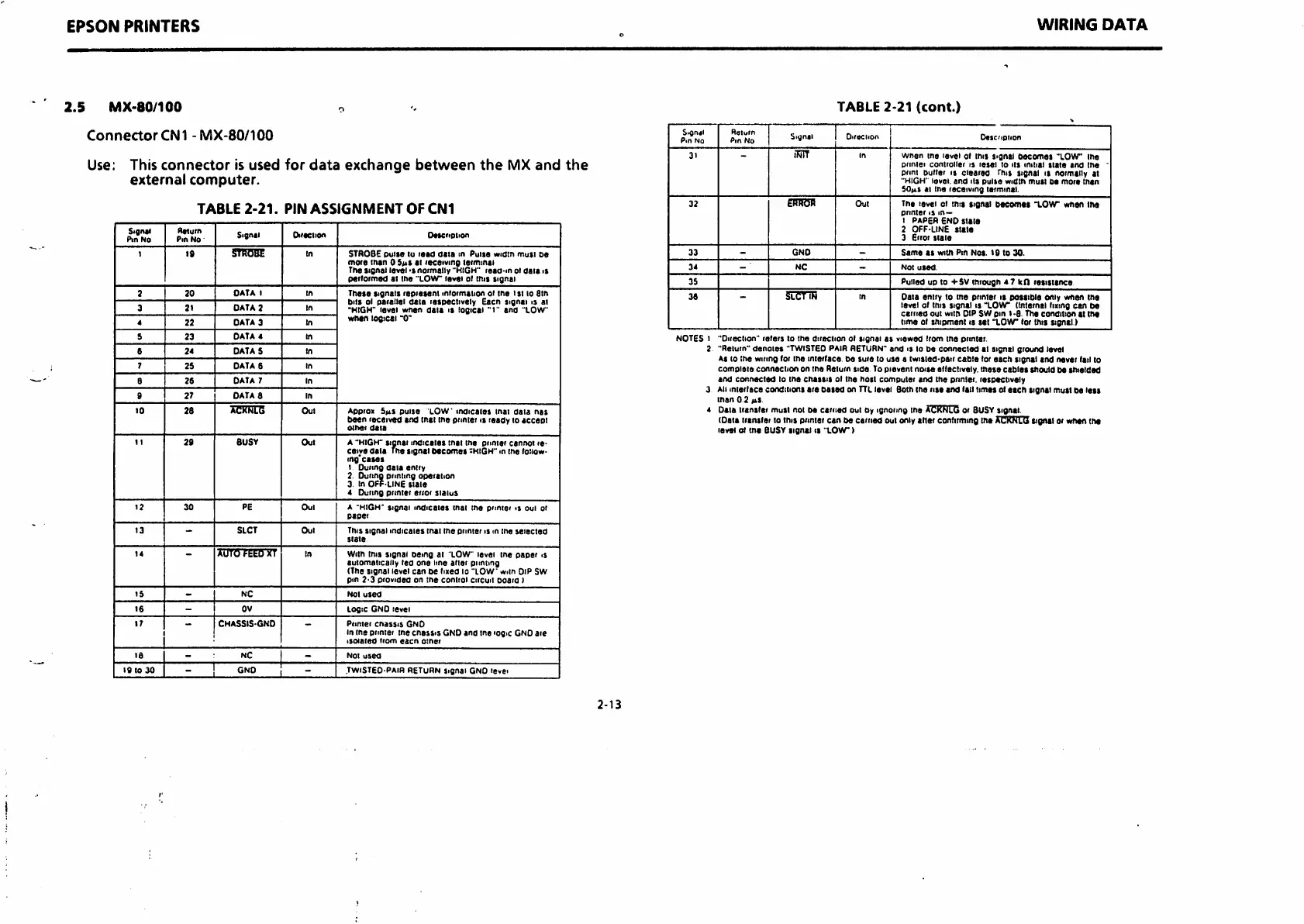
2.5
MX-80/100
o
ConnectorCNl
-MX-80/100
Use: This
connector
is
used
for
data
exchange
between
the
MX
and
the
external
computer.
TABLE
2-21.
PIN
ASSIGNMENT
OF
CNl
Stgnii
Pin
No
Return
Pin
No •
Signti
Direction
OMcriplion
1
19
STROBE
In
STROBE
pulse
tu
read
data
m
Pulse
widin
must
be
more
man 0 Sm* at receiving lermmai
The
signal
level normally "HIGH"
reaa-m
oi
data
is
perlormed
at the
"LOW
level ol this
signal
2
20
DATA
t
in
These
signals
represent
miormation
ot
tne
isi
to Stn
bits ol parallel
data
respectively Eacn signal is at
•HIGH"
level
when
data
is
logical
"i"
and
"LOW
when
logical "0"
3
2t
DATA 2
In
4
22
DATA
3
In
5
23
DATA 4
In
6
24
DATA 5
In
7
2S
DATA
6
In
B
26
DATA 7
in
9 27 DATA 8
in
10
28
ACKkLG
Oul
Appro
SmS
pulse
LOW
indicates
tnai
data
nas
been
received
and
mat
tne printer n
ready
to
accept
other
data
11
29
BUSY
Out
A "HIGH"
stanai
indicates
mat
the
printer
cannot
re
ceive
data
The
signal
becomes
:kiGH"
m tne loiiow-
ing
cases
1 During
oaia
entry
2. During printing operation
3. In
OPALINE
State
4 During printer error
status
12
30
PE
Out
A "HIGH" Signal
indicates
that
the
pnnier
<s oui ol
paper
13
-
SLCT
Oul
This
signal
indicates
that tne printer is m ine
selected
state
14
AUTOFEED XT
In
With ihis
signal
being
at "LOW" levei tne
paper
is
automatically
led
one
line
alter
pnnting
(The
signal
level
can
be
lued
to
"LOW
wiin Dip SW
pin
2-3
provided
on
tne
control
circuit
boaio
I
15
-
NC
Not
used
16
- OV
Logic GND level
>7
CHASSIS-GND
—
Primer
Chassis
GND
In tne printer tne
cnassis
GND and me iog>c GND are
isolated
irom
eacn
other
16
- :
NC
1 -
Not
used
19
to
30
- !
GND
! -
.TWiSTEO-PAiR RETURN Signal GND levei
2-13
WIRING
DATA
TABLE
2-21
(cont.)
S>4n4l
PiA No
Roiurn
Pin
No
Signal
Oi'ttClion
Oescnpiion
31
iRlT
In
wnen
the
level
ol mis
signal
becomes
"LOW
me
piiniei
controller
is
lesei
to
its
initial
state
and
me
~
print Duller is
cleared
This signal is normally at
"HIGH' level,
and
its
pulse
width
must
be
more
man
SO|it
at me receiving terminal.
32
ERROR
Out
The level ol
tmt
signal
becoRiet
"LOW
when the
printer
is
m—
1
PAPER
END
Slate
2
OFF-LINE
state
3
Error
slate
33
-
GND
-
Same
as
with
Pin
Not.
19 to
30.
34
NC
-
Not
used.
35
Pulled up to -fSV miough 4 7 ten
resistance
36
SLCTl^^ in
Data entry to the pnnter is
posttble
only wnen the
level ol this signal is
"LOW
(internal liiing can be
carried
out
with
DIP SW pin
t-8.
The
condition
at
iht
time ol shipment is
stt
"LOW
lor mis signal.)
NOTES 1 "Oitection" refers lo the direction ol
tignai
as
viewed
Iron
tne ptinier.
2 "Return"
denote*
"TWISTEDPAIR RETURN"ar>d is lo be
connected
tl
signal ground level
As to Ihe wiring (or the interlace. De sure to use a twisted-pair
cable
lor
each
signal and never lail to
comoiete
connection
on tne Return
tide
To pievent
noise
ellectiveiy.
tnese
cables
siiould be shielded
and
connected
to tne
cnassts
ol tne nost computer and the printer, respectively
3 All
intedace
conditions are
bated
on TTLlevel Both ine rise and tail limes o<
each
tignU
mutt
be
lest
man
02
iki
4
Data
ttantlei
must
not be
earned
out by ignoring me ACKNLC or BUSY signal.
tOata translet to this piintsr can be
earned
out only alter contirmmg tne
acknlq
Signal w when the
level
oJ
tne
BUSY
signet
is
"LOW)

 Loading...


