L565/L566 Series Revision A
Disassembly/Reassembly Detailed Disassembly/Reassembly Procedure for each Part/Unit 48
Confidential
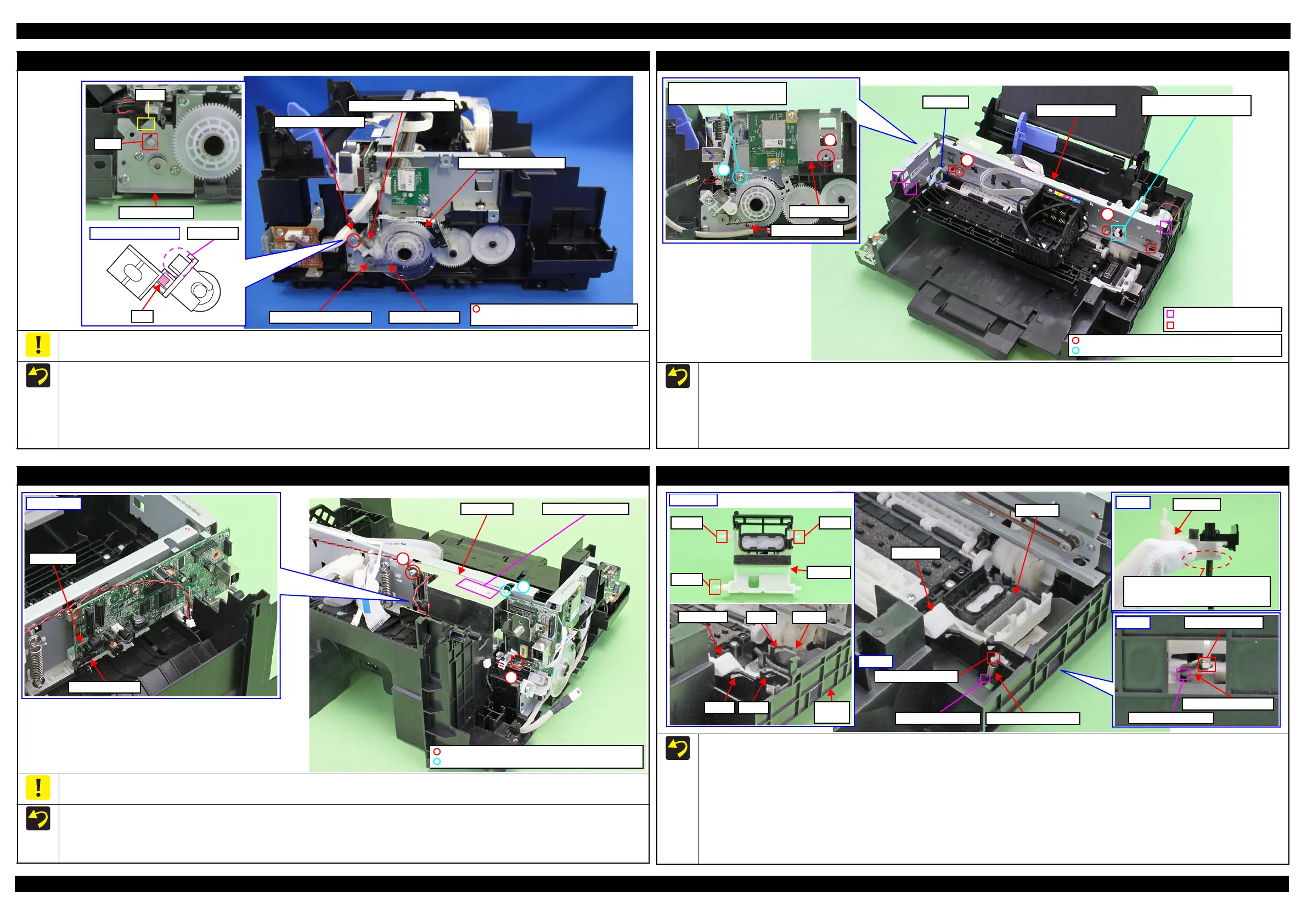
PF Driven Pulley Assy / PF Timing Belt
Do not hold the PF Driven Pulley Assy when securing it with the screw in order to prevent applying improper tension to the PF Timing Belt.
When installing the PF Driven Pulley Assy, follow the procedure below.
1. Align the rib of the PF Driven Pulley Assy with the hook of the PF Motor Frame, and install the PF Driven Pulley Assy.
2. Attach the Compression Spring 5.07 to the protrusion of the PF Driven Pulley Assy and the dowel of the PF Motor Frame.
3. Attach the PF Timing Belt in the order of the pinion gear of the PF Motor, PF Driven Pulley and Combination Gear 29.2,42.
4. Rotate the Combination Gear 29.2,42 clockwise three times to confirm the PF Timing Belt is correctly attached, and then secure the PF Driven
Pulley Assy with the screw and washer to the PF Motor Frame.
Dowel
Hook
PF Motor Frame
Protrusion
Rib
PF Driven Pulley Assy
C.B.S-TITE(P2) SCREW 3x6 F/ZN-3C
P.W. 3.4x0.43x7 (7 ± 1 kgf·cm)
Pinion gear of PF Motor PF Timing Belt
Compression Spring 5.07
PF Driven Pulley Assy
Combination Gear 29.2,42
Main Frame Assy
Before installing the Main Frame Assy, shift the Change Lever back to the rear.
When installing the Main Frame Assy, make sure of the following.
• The Change Lever must not interfere with the Main Frame.
• The above shown ribs and grooves, positioning holes and dowels are correctly aligned.
• The section A of the Main Frame Assy is not deformed.
Tighten the screws in the order indicated in the figure above.
3
4
PF Motor Frame
Main Frame
Align the screw holes of Main
Frame and PF Motor Frame.
1
2
Section A
Main Frame Assy
Change Lever must not
interfere with Main Frame.
C.B.P-TITE SCREW 3x10 F/ZN-3C (6 ± 1 kgf·cm)
C.B.S-TITE SCREW 3x6 F/ZN-3C (6 ± 1 kgf·cm)
Rib and groove
Positioning hole and dowel
Main Board/Shield Plate
Do not damage or contaminate the MAC Address Label.
Install the Main Board with the PE Sensor Lever to the rear. After installing the Main Board, make sure the lever part of the PE Sensor Lever is
aligned with the slit of the PE Sensor.
Attach the MAC Address Label to the Shield Plate on the position indicated in the figure above.
Tighten the screws of the Shielded Plate in the order indicated in the figure above.
MAC Address LabelShield Plate
Main Board
PE Sensor Lever
PE Sensor
1
2
3
C.B.S-TITE SCREW 3x6 F/ZN-3C (6 ± 1 kgf·cm)
C.B.S-TITE SCREW 2x4 F/ZN-3C (2 ± 0.5 kgf·cm)
Cap Lever / Cap Assy
When installing the Cap Lever/Cap Assy, follow the procedure below.
1. Attach the Cap Lever to the Frame Base, and attach one end of the Extension Spring 0.65 to the hook of the Frame Base.
2. Connect the tube of the Pump Unit to the joint on the bottom of the Cap Assy. Then, viewing from the side, confirm the marking (10 ± 1 mm
from the tube end) on the tube is covered by the Cap Slider.
3. Insert the shaft A of the Cap Assy through the hole of the Cap Lever to the hole A of the Frame Base.
4. Insert the shaft B of the Cap Assy through the cutout of the Frame Base and to the hole B of the Frame Base.
5. Insert the shaft C of the Cap Assy to the hole C of the Frame Base.
6. Using a “spring hook jig” (p 18), attach the other end of the Extension Spring 0.65 to the hook of the Cap Assy.
7. Attach the Extension Spring 1.329 to the hooks of the Cap Lever and Frame Base.
Cap Lever
Extension Spring 1.329
Cap Assy
Extension Spring 0.65
Hook of Cap Assy
Hook of Frame Base
Step 6
Shaft BShaft A
Shaft C
Cap Assy
Step 2
Make sure the marking (10 ± 1 mm
from the tube end) on the tube cannot
be seen when viewed from the side.
Cap Slider
CutoutHole BCap Lever
Frame
Base
Hole A
Hole C
Step 1, 3-5
Hook of Frame Base
Hook of Cap Lever
Step 7
 Loading...