L565/L566 Series Revision A
Disassembly/Reassembly Routing FFCs/cables 53
Confidential
2.4 Routing FFCs/cables
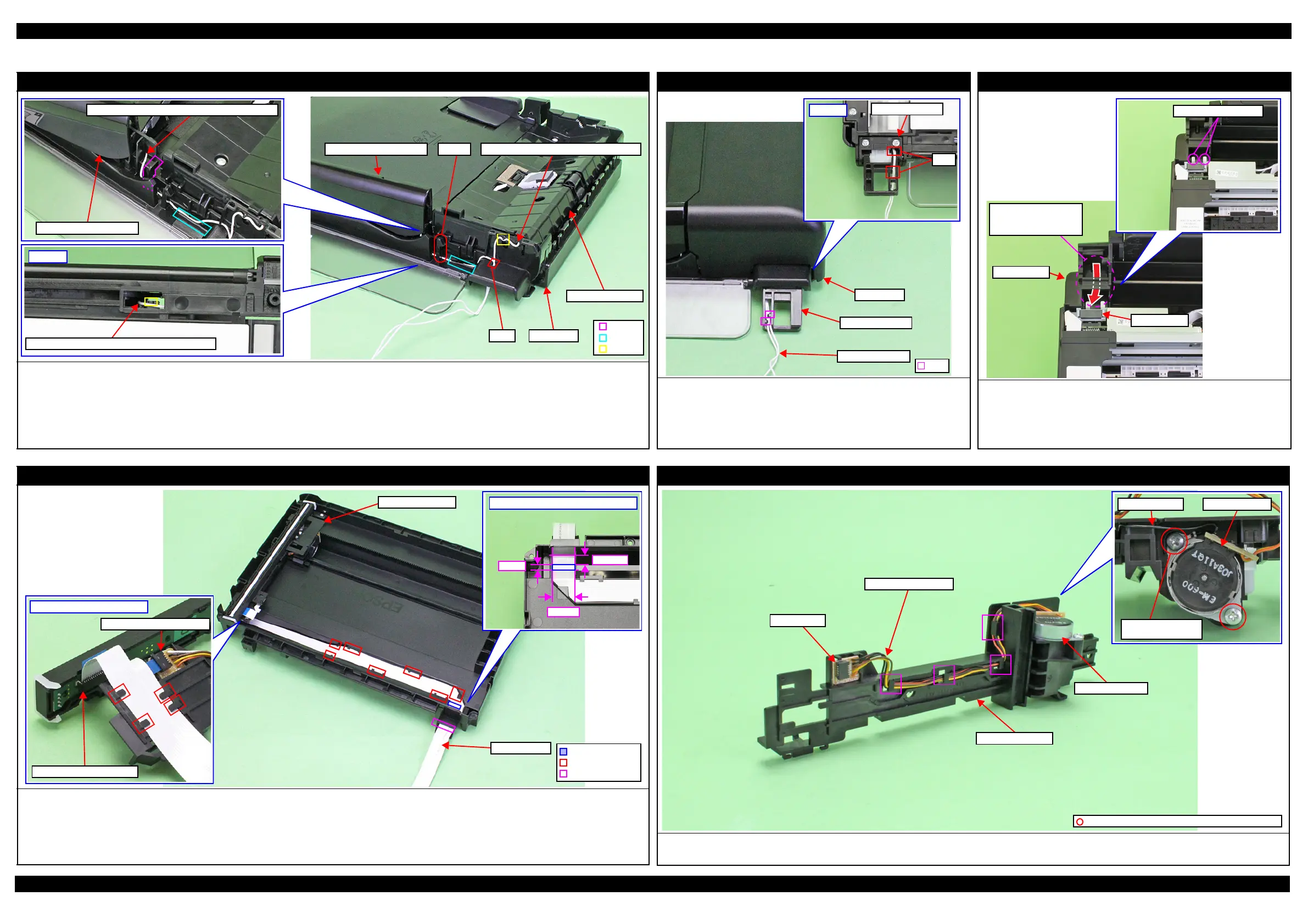
ADF Frame Assy / ADF Document Support
Rotate the grounding wire of the ADF Frame Assy and ADF Document Support(x2) as follows.
Grounding wire of the ADF Frame Assy
Hang the grounding wire the dowel (x3) and route through the hole of the ADF Base.
Grounding wire of the ADF Document Support
1. Route along the rib A of the ADF Base and hang the dowel on the bottom of the ADF Base.
2. Route along the inside the hook and rib B of the ADF Base and route through the hole of the ADF Base.
Grounding wire of the ADF Document Support
ADF Document Support
Bottom
Grounding wire of the ADF Document Support
ADF Base
Rib A
Rib B
Dowel
Hole
Grounding wire of the ADF Frame AssyHook
ADF Frame Assy
ADF Document Support
ADF Hinge Left
Route the grounding wire (x2) of the ADF Frame Assy/ADF Document
Support through the ADF Hinge Left as follows.
1. Route the grounding wire (x2) through the hole (x2) of the ADF Hinge Left.
2. Install the ADF Hinge Left to the ADF Base. Hang the grounding wire
(x2) on the rib (x2) of the ADF Hinge Left and route.
Grounding wire
Hole
ADF Hinge Left
Bottom
Hol
ADF Base
ADF Hinge Left
Rib
ADF/Scanner Unit
Scanner FFC
Insert the hole of the Housing Left and connect the connector (CN11) of
the Main Board through the ferrite core.
Grounding wire (only ADF compatible model)
Insert the hole of the Housing Left and connect the frame of the FAX Assy.
Route the Scanner FFC
inserting the hole of the
Housing Left.
Housing Left
Frame of FAX Assy
Ferrite core
Scanner FFC
Route the Scanner FFC as follows.
1. Insert the Scanner FFC through the hole of the Scanner Housing Lower in the direction shown above, and then secure the FFC with double-sided tape on
position with the standard shown in the figure above.
2. Route the FFC through the ribs (x7) of the Scanner Housing Lower taking care not to damage the FFC.
3. Route the FFC through the ribs (x5) on the bottom of the Scanner Carriage taking care not to damage the FFC.
4. Connect the Scanner FFC to the Relay Board and CIS Module as shown above.
Bottom of Scanner Carriage
Connector of Relay Board
Connector of CIS Module
Standard for attaching double-sided tape
7.5 mm
5 mm
20 mm
Scanner Carriage
Scanner FFC
Hole
Rib
Double-sided tape
Scanner Motor
Route the Scanner Motor cable through the hooks (x4) of the Scanner Motor as shown above.
Secure the grounding wire of the Relay Board and the Scanner Motor together with the screw as show above.
Relay Board
Scanner Motor cable
C.B.P-TITE SCREW 3x10 F/ZN-3C (5 ± 1 kgf·cm)
Grounding wire
Scanner Motor
Screw it with
grounding terminal
Scanner Motor
Scanner Carriage

 Loading...