Maintenance 6. Joint #2
LS20-B Rev.4 105
eduction
ear Unit
Push down the shaft to its lower limit while pressing the brake release switch.
Be sure to keep enough space and prevent the
end effector
hitting any peripheral
equipment.
The brake release switch is applied to both Joints #3 and Joint #4.
When the brake release switch is pressed, the respective brakes of the Joint #3 and Joint
#4 are
released simultaneously.
shaft falling and rotating while the brake release switch is
because the shaft may be lowered by the weight of an end effector.
generator from the Joint #2 motor.
Follow the removal steps in Maintenance: 6.1 Replacing Joint #2 Motor.
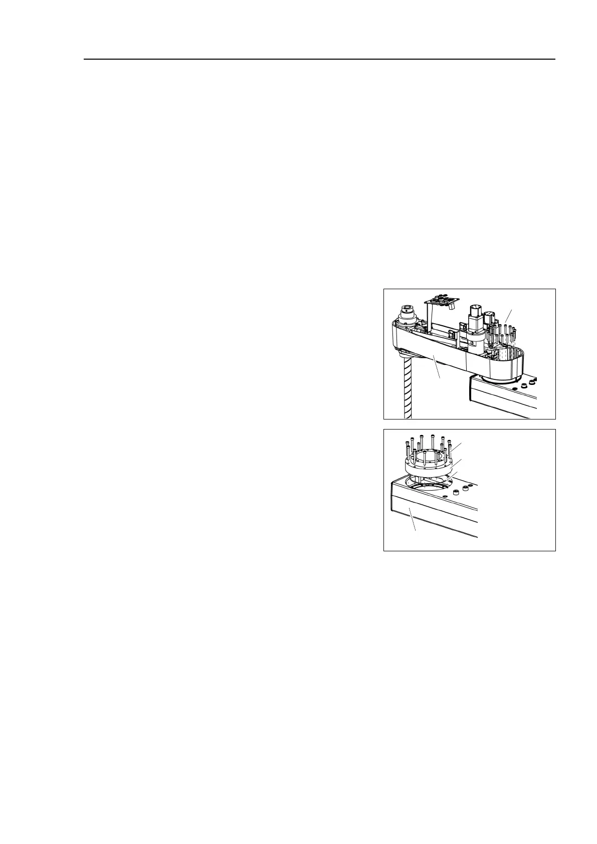
Remove the Arm #2 mounting screws to
remove it from the
reduction gear unit.
reduction gear unit from the
Arm #1 by removing the screws that
mounts the reduction gear unit on the Arm
#1.
-ring between the Arm #1 and
Be careful not to lose the removed O
-ring.
Arm #1
12-M5×40
Reduction Gear Unit
O ring
 Loading...


