EPSON Perfection 1250/1250 PHOTO Appendix
50
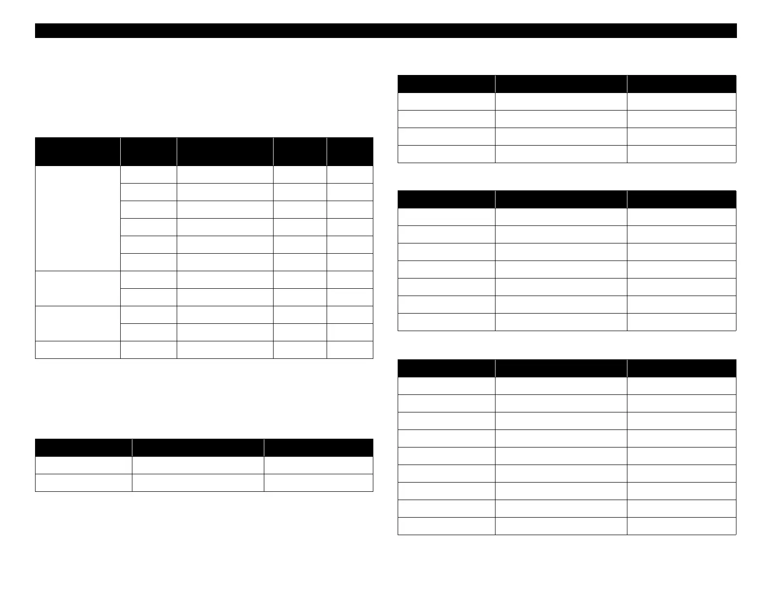
6.3.2 Connector Summary
Connectors used in the scanner are listed below. For their pin assignments,
refer to the tables listed in the right-hand column.
6.3.3 Connector Pin Assignments
The pin assignments for circuit board connectors are shown in the following
tables.
Table 6-3. Main Circuit Board CN1
Table 6-4. Main Circuit Board CN2
Table 6-5. Main Circuit Board CN3
Table 6-6. Main Circuit Board CN4
Table 6-2. Connector Summary
Board Connector Function No. of Pins
Ref.
Table
Main circuit board
CN1 AC input 2 6-3
CN2 USB connector 6 6-4
CN3 Panel circuit board 7 6-5
CN4 CCD circuit board 23 6-6
CN5 CR motor 5 6-7
CN6 TPU 7 6-8
CCD circuit board
CN1 Main circuit board 23 6-3
CN2 Inverter circuit board 2 6-9
Inverter circuit
board
CN1 CCD circuit board 2 6-9
CN2 Lamp 2 6-10
Panel circuit board CN1 Main circuit board 7 6-5
Pin No. Signal I/O
1 +15VDC I
2GND —
Pin No. Signal I/O
1VCC I
2 –Data I/O
3+Data I/O
4GND —
Pin No. Signal I/O
15V O
2 GREEN O
3RED O
4Push–SW1 I
5Push–SW2 I
6Push–SW3 I
7Push–SW4 I
Pin No. Signal I/O
1+15V O
2GND —
3B# I
4B I
5A# I
6A I
7GND —
8 SENSEB O
9 SENSEA O
 Loading...