SC-P600 Revision D
Disassembly/Reassembly Detailed Disassembly/Reassembly Procedure for each Part/Unit 20
SE Group Confidential (Related Staff Only)
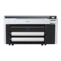
Panel Unit
When disassembling the Panel Unit, take off the fixed screws (x4)
of the shafts that of Housing Panel Rear. Then remove the unit
from the Housing Upper Support Assy by turning the whole unit
forward.
Pane Cover Rear
Ferrite Core
Panel SUB Board
C.B.P-TITE SCREW,3X8,F/ZN-3C (6 ± 1 kgf·cm)
Remove the Panel
Cover Rear
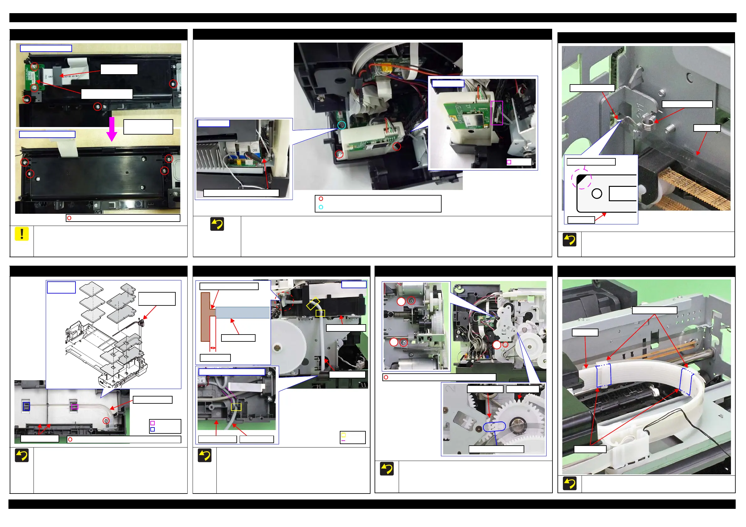
CR Scale
Attach the CR Scale to the spring leg with the black triangle
mark upward on the left side of the printer.
Attach the Torsion Spring, 0.39 as shown above.
CR Scale
Torsion Spring, 0.39
CR Scale
Black triangle mark
Waste Ink Tube / Waste Ink Pad
When installing the Waste Ink Tube/Waste Ink Pads (x10),
confirm the shapes of them and install them in the order shown
above.
When installing the Waste Ink Tube, route it through the
groove of the Waste Ink Pads, and insert the end of the shorter
tube to the section A and longer one to the section B.
Section B
Section A
Waste Ink Tube
/ Tube Holder
Waste Ink Pads
C.B.P-TITE SCREW,3X8,F/ZN-3C (6 ± 1 kgf·cm)
Waste Ink Tube
Installation
order
Decomp Pump Assy
When connecting the Decomp Tube to the joint of the I/C
Holder Unit, make sure the gap between the end of the Decomp
Tube to the base of the joint is 1 mm or less, and then secure
the tube with the hooks (x2).
Route the Decomp Tube through the groove of the Lower
Housing and secure the tube with the hook.
1 mm or less
Joint for Decomp Tube
Decomp Tube
Left inside of Lower Housing
Decomp Tube
I/C Holder Unit
Lower Housing
Decomp Tube
Groove
Left side
APG Assy
When installing the APG Assy, align the marks on the Spur
Gear,14.4 and PG Cam Left to match their phases as shown
above.
Tighten the screws in the order indicated in the figure above.
PG Cam LeftSpur Gear,14.4
Align triangle marks.
3
C.B.S-TITE SCREW,3X6,F/ZN-3C(8
±
1kgf·cm)
Ink Tube Holder
When installing the Ink Tube Holders (x2), install them on the
locations where the acetate tape (x2) is attached on the Ink Tube.
Ink Tube Holders
Ink Tube
Acetate Tape
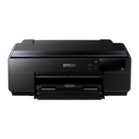
Wireless LAN Module Assy
When installing the Wireless LAN Module Assy, put the following four cables through a hook of the part right side.
• Printer Cover Open Sensor cable
• I/C Holder Unit Cover Open Sensor cable
• Mist Board cable
• ASF PE Sensor Cable
C.B.P-TITE SCREW,3X10,F/ZN-3C (6±1 kgf
·
cm)
C.B.S-TITE SCREW,3X6,F/ZN-3C (6±1 kgf
·
cm)
Wireless LAN Module cable