SC-P600 Revision D
Disassembly/Reassembly Detailed Disassembly/Reassembly Procedure for each Part/Unit 21
SE Group Confidential (Related Staff Only)
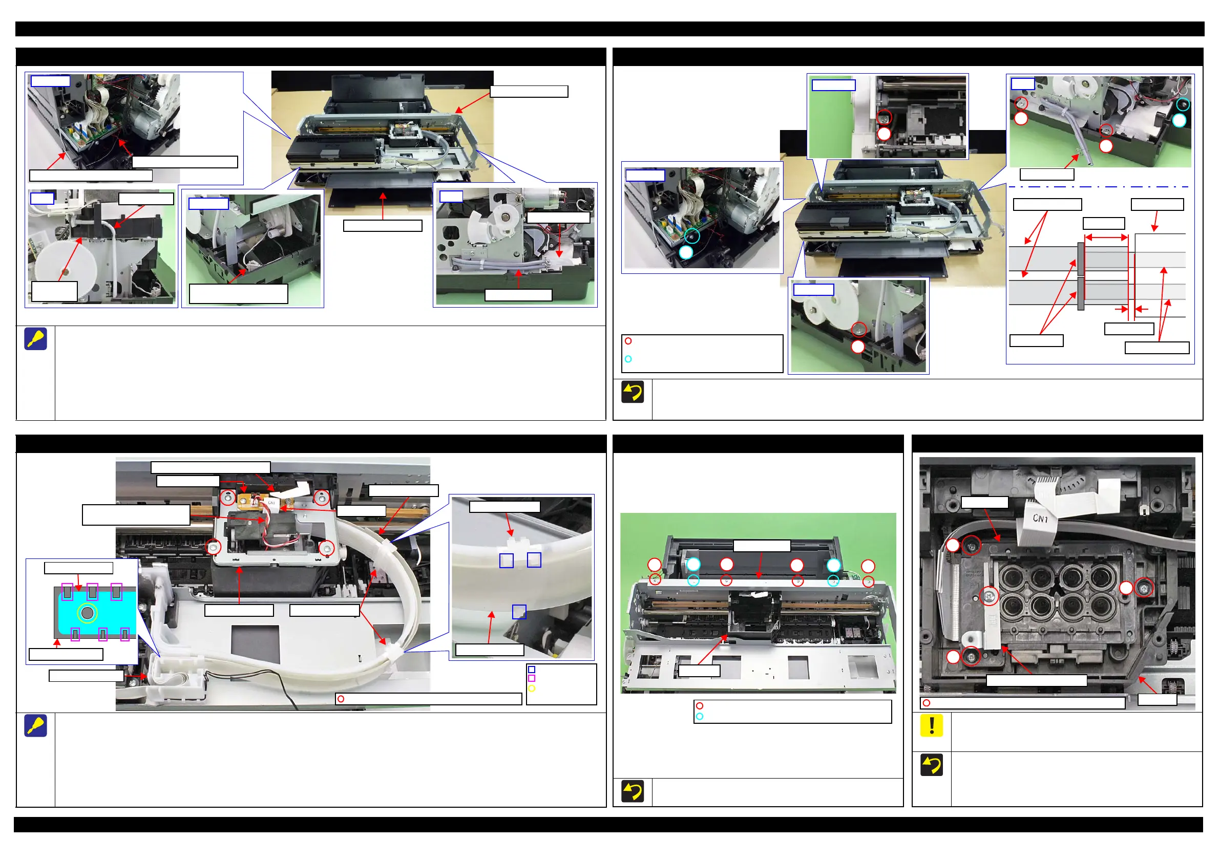
Printer Mechanism (1)
Disconnect the following cables/tubes when removing the Printer Mechanism from the Lower Housing Assy.
Disconnect the following cables from the connector on the Main Board.
• Stopper Tray Sensor Relay Cable (CN1)
• Decomp Pump Motor Cable (CN22)
Disconnect the Decomp Tube.
Disconnect the Ink System Tube from the Waste Ink Tube.
Disconnect the relay connector of the Stopper Tray Sensor Relay Cable.
Front left
Connector of Stopper Tray
Sensor Relay Cable
Rear left
Stopper Tray Sensor Relay Cable
Decomp Pump Motor Cable
Left
Decomp Tube
I/C Holder
Unit
Right
Ink System Tube
Waste Ink Tube
Lower Housing Assy
Printer Mechanism
Printer Mechanism (2)
Tighten the screws in the order indicated in the figure above.
When connecting the Ink System Tube to the Waste Ink Tube, make sure the gap between the end of the Ink System Tube and the Tube Holder is
1 mm or less, and attach the Tube Clamp 5
±
2 mm from the end of the Ink System Tube.
Tube Clamp
C.B.S-TITE(P2)SCREW,3X10,F/ZN-3C
(6 ± 1kgf·cm)
C.B.P-TITE SCREW,4X8,F/ZN-3C
(8 ± 1kgf·cm)
1 mm or less
5
±
2 mm
Ink System Tubes
Tube Clamps
Tube Holder
Waste Ink Tubes
CR Support Plate
When removing the CR Support Plate, follow the procedure below.
1. Disconnect the following cables/FFCs from the connectors on the CR Relay Board.
• Ink Selector Motor Cable (CN2) • Ink Selector Sensor Cable (CN5)
• Head FFC (CN1) • CR Encoder / PW Sensor FFC (CN6)
2. Remove the screws (x4) that secure the CR Support Plate.
3. Release the hooks (x3 each) of the Ink Tube Holders (x2) and remove the Ink Tube Guide from the Ink Tube Holders (x2).
4. Release the Ink Tube Guide from the ribs (x6) and dowel of the Cable Holder Front, and remove the CR Support Plate.
Ink Tube Holder
Ink Tube Guide
Ink Tube Guide
Cable Holder Front
Positioning hole
and Dowel
Rib
Hook
Cable Holder Front
CR Support Plate
Ink Selector Motor Cable
Ink Selector Sensor Cable
CR Encoder / PW Sensor FFC
Head FFC
Ink Tube Holders
Ink Tube Guide
C.B.P-TITE SCREW,3X8,F/ZN-3C (6 ± 1 kgf·cm)
CR Relay Board
CR Guide Plate
Tighten the screws in the order indicated in the figure above.
C.B.S-TITE(P4)SCREW,3X6,F/ZN-3C(8
±
1kgf·cm)
C.B.S-TITE SCREW,2.5X6,F/ZN-3C(4
±
CR Unit
CR Guide Plate
1
23
45
6
Printhead / Printhead Mounting Plate
Do not use the electric screwdriver when installing the Printhead
and/or the Printhead Mounting Plate. Doing so applies extra force
when tightening the screw and affects the platen gap.
When installing the Printhead, follow the procedure below.
1. Temporarily tighten the screws (x3) and loosen them half turn.
2. Press the Printhead to the rear of the printer, and tighten the
screws (x3) in the order indicated in the figure above.
2
1
3
CR Unit
Printhead
C.B.P-TITE SCREW,2.5X8,F/ZN-3C(3.5
±
0.5kgf·cm)
Printhead Mounting Plate