SC-P600 Revision D
Disassembly/Reassembly Detailed Disassembly/Reassembly Procedure for each Part/Unit 25
SE Group Confidential (Related Staff Only)
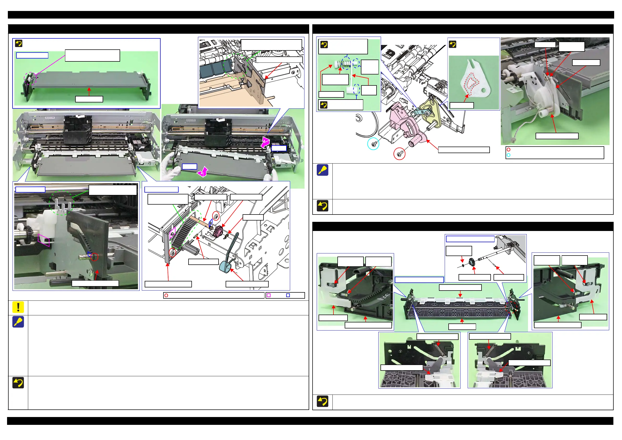
Front Tray Assy
When disassembling/reassembling the Front Tray Assy, there are some locations where the frame and the Front Paper Guide Assy may interfere.
Therefore, be careful not to deform the frame when working.
When removing the Front Tray Assy, follow the procedure below.
1. Remove the screw that secure the Mist Board Assy.
2. Remove the Torsion Spring, 187.9 on the right side of the Front Tray Assy.
3. Remove the E-ring, 3, and remove the Spur Gear, 14.4 and Parallel Pin, 1.5.
4. Remove the screws (x3) that secure the Front Tray Assy.
5. Release the hook and dowel of the Front Left Tray Guide from the frame and slide it to the front of the printer, and then lift the left side of the
Front Tray Assy.
6. Release the hook and dowels (x2) of the Front Right Tray Guide from the frame and slide it to the front of the printer while avoiding the Front Paper
Guide Assy, and then remove the Front Tray Assy by pulling out the Front Tray Shaft and Front Right Tray Guide from the hole of the frame.
Reassemble the Front Tray Assy with the Front Tray raised. After reassembly, make sure the Front Tray Assy is secured with the hooks and
dowels, and then secure it with the screws.
After reassembling the Front Tray Assy, confirm the Torsion Spring, 187.9 is correctly attached.
Before reassembling the Tray Support Assy/Front Tray, confirm the Washer,3.1X0.5X5.4 (x2) and Washer,26X0.5X4.7 (x2) are correctly
attached.
Right: Step 2-4
E-ring, 3
Spur Gear, 14.4
Torsion Spring, 187.9
Parallel Pin, 1.5
Front Tray Shaft
The location where
frame may interfere.
Front Right Tray Guide
Left: Step 4, 5
Front Left Tray Guide
The location where frame
may interfere.
The location where Front Paper
Guide Assy may interfere.
Front Right Tray Guide
Dowel
HookC.B.P-TITE SCREW,3X6,F/ZN-3C (4 ± 0.5 kgf·cm)
Front Tray
Front Tray Assy
The Front Tray is raised if
the gear is in this position.
Reassemble the Front Tray Assy with the Front Tray raised.
Stopper Tray Unit
When removing the Stopper Tray Unit, follow the procedure below.
1. Remove the Torsion Spring, 187.9.
2. Remove the screws (x2) that secure the Stopper Tray Front Assy and remove the Stopper Tray Front Assy.
3. Remove the Lever Link with Cover Spring and Compression Spring.
4. Remove the E-ring, 3 and Washer, 4.3X0.8X8, and remove the Stopper Tray.
When attaching the Cover Spring to the Link Lever, attach it as shown above.
After reassembling the Stopper Tray Unit, confirm the Torsion Spring, 187.9 is correctly attached.
Compression
Spring
This side is facing
to frame.
Attach Cover spring/
Compression spring
to shaft (longer side).
Cover Spring
Shaft
(shorter
side)
Link
Lever
Align shaft (shorter side)
of Link Lever to cam
groove of Stopper Tray.
E-ring, 3
Washer,
4.3X0.8X8
Stopper Tray
Torsion Spring, 187.9
C.B.P-TITE SCREW,3X8,F/ZN-3C(4 ± 0.5kgf·cm)
C.B.S-TITE SCREW,3X6,F/ZN-3C(8 ± 1kgf·cm)
Tray Support Assy / Front Tray
When reassembling the Front Tray Assy, install each part as shown above, and secure them with their dedicated washer, parallel pin, and extension spring.
Before reassembling the Tray Support Assy/Front Tray, confirm the Washer,3.1X0.5X5.4 (x2) and Washer,26X0.5X4.7 (x2) are correctly attached.
EJ Link Left
Front Left Tray Guide
Washer,
26X0.5X4.7
Washer,
3.1X0.5X5.4
Extension Spring, 0.70
Tray Support Assy
EJ Link Right
Washer,
26X0.5X4.7
Front Right Tray Guide
Washer,
3.1X0.5X5.4
Extension Spring, 0.70
Tray Support Assy
Gear section of Front Tray
Washer,
3.1X0.5X5.4
Parallel Pin, 1.5Spur Gear, 14.4
Tray Support Assy
Back of Front Tray Assy
Front Tray
 Loading...