SC-P600 Revision D
Disassembly/Reassembly Detailed Disassembly/Reassembly Procedure for each Part/Unit 24
SE Group Confidential (Related Staff Only)
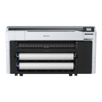
CR Unit
Be careful not to let the grease of the CR Shaft adhere to the Timing Belt of the CR Unit.
When removing the CR Unit, follow the procedure below.
1. Remove the screws (x2) that secure the CR Motor, and remove the CR Motor from the frame.
2. Mark the contact point on the Parallelism Adjust Bushing with the frame. (p 50)
3. Remove the PG Torsion Spring Left / Right.
4. Loosen the screw that secure the Parallelism Adjust Bushing, and turn the Parallelism Adjust Bushing in the direction of the arrow shown above.
5. Remove the CR Shaft Spacer.
6. Lift the CR Shaft, and move both ends of it to the dent of the frame.
7. Remove the Left CR Shaft Mounting Plate.
8. Remove the Washer, 6.9X0.5X10.4 (x1 each) that secure the PG Cam Left/Right, and remove the PG Cam Left/Right from the CR Shaft.
9. Slide the CR Shaft to the left to disengage it from the frame, and from the right end of the CR Shaft, remove the Right CR Shaft Mounting Plate,
Washer, 8.2X0.5X15, and Leaf Spring, 8.2X0.25X15 in order.
10. Remove the left end of the CR Shaft from the frame, and remove it together with the CR Unit.
11. Remove the CR Shaft from the CR Unit.
When installing the CR Motor, install it by referring to " CR Motor (p23)".
Be careful not to mistake the PG Torsion Spring Right and PG Torsion Spring Left when installing them because they look alike.
Make sure to install the Parallelism Adjust Bushing correctly to the location with the marking drawn when removing it.
Right
PG Torsion Spring Right
Step 8
PG Cam Right
Washer,
6.9X0.5X10.4
Step 3
Left
PG Torsion Spring Left
Step 3
C.B.S-TITE(P4) SCREW,3X10,F/ZN-3C
Step 4
Parallelism
Adjust Bushing
PG Cam Left
Step 8
Washer,
6.9X0.5X10.4
Left
CR Shaft Spacer
Step 5
Dent
Step 6
CR Shaft
Left CR Shaft
Mounting Plate
Step 7
Right
Dent
Step 6
CR Shaft
Step 9
Right CR Shaft Mounting Plate
Washer,
8.2X0.5X15
Leaf Spring,
8.2X0.25X15
CR Motor
Step 1
CR Shaft
CR Unit
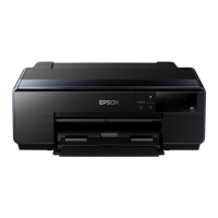
C.B.SCREW,3X4,F/ZN-3C (4 ± 0.5 kgf·cm)
Timing Belt
ASF Assy
Tighten the screws in the order indicated in the figure above.
Attach the terminal of the grounding wire in the direction shown in the “Cross-section” figure.
ASF Assy
Grounding
wire
Main Frame
C.B.S-TITE(P4)SCREW,3X8,F/ZN-3C(8
±
C.B.S-TITE SCREW,3X6,F/ZN-3C(8
±
1kgf·cm)
Cross-section
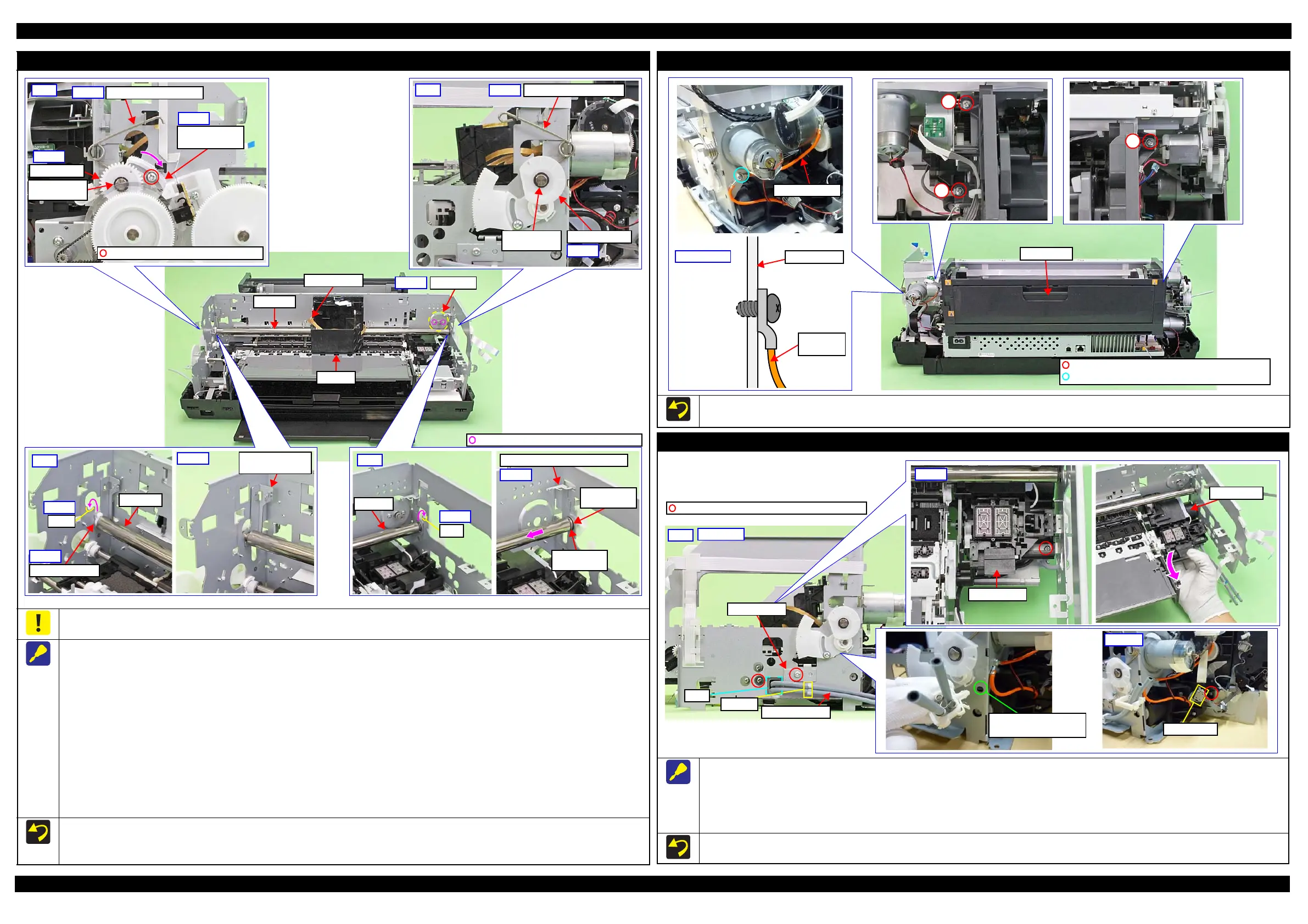
Ink System
When removing the Ink System, follow the procedure below.
1. Release the Ink System Tube from the clamp A and pull out from the hole of the frame.
2. Release the Pump Motor Cable from the connector.
3. Remove the screws (x2) that secure the Support Plate, and remove the Support Plate.
4. Remove the screws (x2) that secure the Ink System, and remove it downward while avoiding the frame.
When securing the Ink System Tubes (x2) with the clamp A, make sure to arrange the shorter one to the bottom as shown.
Clamp A
Hole
Ink System Tube
Support Plate
C.B.S-TITE SCREW,3X6,F/ZN-3C (8 ± 1 kgf·cm)
Right
A hole to attach a clamp
to fix the Ink Tube
Connector
Step 1,3,4
Step 2,4