SC-P600 Revision D
Disassembly/Reassembly Routing FFCs/cables 29
SE Group Confidential (Related Staff Only)
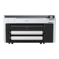
Rear left of printer (1)
CN # Name CN # Name CN # Name
CN1
Stopper Tray
Open Sensor Relay Cable
CN9 Head FFC CN19 CSIC FFC
CN10 Head FFC
CN20
Roll Paper Guide
Open Sensor Cable
CN2 CSIC FFC CN11 Head FFC
CN3 PictBridge Holder Cable CN12 CR Relay Board FFC CN22 Decomp Motor Cable
CN4 Panel FFC CN13 Mist Board Cable CN115 CR Motor Cable
CN5 Panel FFC CN15 CSIC FFC CN116 PF Motor Cable
CN6 ASF Relay Board FFC CN16
Printer Cover
Open Sensor Cable
CN117 Pump Motor Cable
CN7 Wireless LAN Module Cable
CN17
I/C Holder Unit Cover
Open Sensor Cable
CN118 APG Motor Cable
CN8 Head FFC CN119 ASF Motor Cable
Route Panel FFC
over ASF Assy.
Reference line
Double-sided tape
PF Encoder FFC
Panel FFC
Around ASF Relay Board
Route PE Sensor Cable
under rib of ASF Assy.
ASF Relay Board
APG HP Sensor Cable
APG Position
Sensor Cable
Double-sided tape
PF Encoder FFC
Secure PF Motor
Cable with clamp.
ASF PE
Sensor Cable
Pump Motor
Cable
CR Motor
Cable
Roll Paper Guide
Open Sensor Cable
APG Motor Cable
PF Motor Cable
ASF Motor
Cable
Mist Board
Cable
Printer Cover
Sensor Cable
I/C Holder
Cover Sensor
Cable
Head FFC/CSIC FFC
Stopper Tray Open Sensor Relay Cable:
Pull out through hole of Lower Housing and make
one turn around hook, then connect to Main Board.
Decomp Motor Cable
CN2
CN15
CN11
CN9
CN8
CN10
CN12
CN4
CN5
CN19
CN1
CN7
CN20
CN6
CN118
CN115
CN119
CN117
CN116
CN22
CN16CN17
CN13
CN3
When routing the following FFCs,
route them through groove of ASF
Assy under Roll Paper Guide Assy.
Head FFC
CSIC FFC
Panel FFC
Hook
Refer below for the connector layout on the Main Board for the cables/FFCs. The connector numbers are marked on each FFC, therefore, make sure of it when
connecting them.
ASF Relay Board FFC
CN #
Name
CN #
Name
CN #
Name
CN1
ASF Relay
Board FFC
CN2
PE Sensor
Cable
CN6
PF Encoder
FFC
ASF Assy
Hole
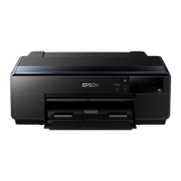
Rear left of printer (2)
Fold the Head FFC / CSIC FFC along the fold line, and route them through the ribs (x6) of the Cable Holder Rear, Cable Holder Left, and the ribs (x3) on
the left side of the I/C Holder Unit.
Route the CSIC FFC over the Head FFC and secure the CSIC FFC with double-sided tape at the points shown in the figure above.
Route Head FFC through groove on left side of I/C
Holder Unit, and route it to Cable Holder Left.
Route CSIC FFC through groove of Cable Holder
Left, and route it to Cable Holder Rear.
Double-sided tape
Rib
Head FFC
CSIC FFC
Cable Holder Rear
Double-sided tape
Cable Holder Left
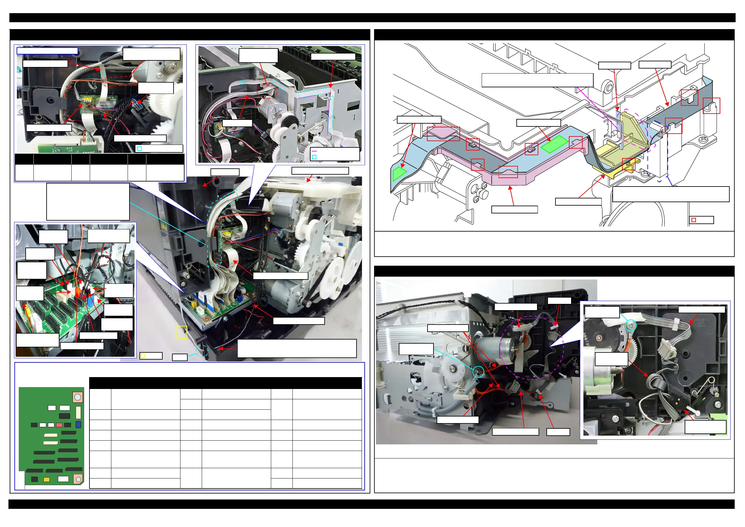
Rear right of printer
Fix the grounding wires with screws in two places of the ASF Motor and the Ink System.
Connect the ASF Motor Cable to the ASF Motor Relay Cable, and then secure it with the clamp A.
Be careful not to let the ASF Motor Relay Cable interfere with the Roll Paper Guide Open Sensor when routing it.
Connect the Pump Motor Cable to the Pump Motor Relay Cable, and then secure it with the clamp B.
Clamp A
ASF Motor Cable
ASF Motor Cable
Clamp B
Roll Paper Guide
Open Sensor
CR Motor Cable
Pump Motor Cable
Screw with
ASF Motor
ASF Motor
Relay Cable
Screw with
Ink System
Grounding wire