SC-P600 Revision D
Disassembly/Reassembly Routing FFCs/cables 30
SE Group Confidential (Related Staff Only)
Mist Board Assy / Right side of the Main Frame
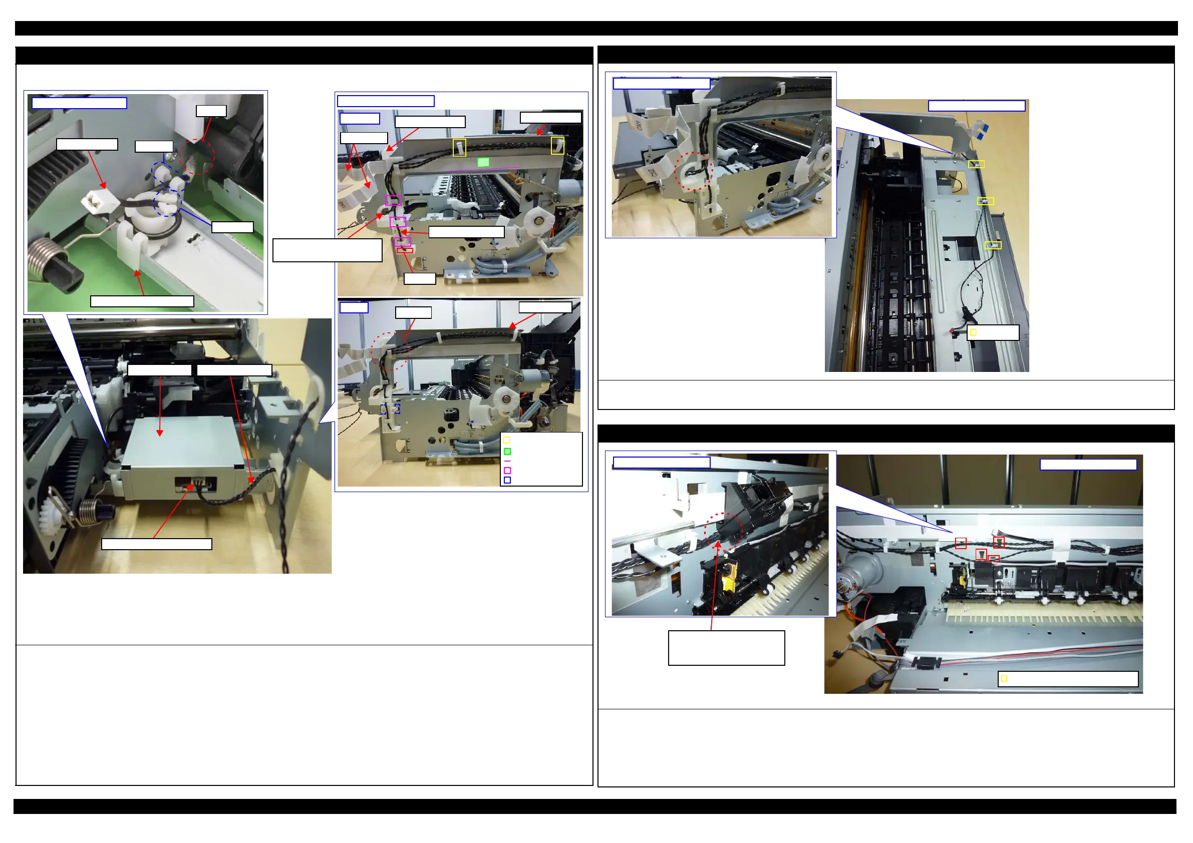
When routing the FFCs/cables on the Mist Board Assy and the FFC on right side of the Main Frame, follow the procedure below.
1. Before installing the Cable Holder Right to the Main Frame, route the Mist Board Cable through the groove and ribs (x3) of the Cable Holder Right.
2. Route the Panel FFC along the reference line of the Main Frame, and secure it to the Main Frame with double-sided tape.
3. Route the Mist Board Cable through the hole of the Main Frame.
4. Secure the I/C Holder Unit Cover Open Sensor Cable and Printer Cover Open Sensor Cable with the clamps (x2) and ribs (x2), and then route these
cables through the hole of the Main Frame.
5. Engage the section A of the Cable Holder Right to the Main Frame as shown above, and then secure the Cable Holder Right to the Main Frame with the
hooks (x2).
6. Connect the Mist Board Cable to the Mist Board Cable connector.
Pull out the electrode cable from the cutout of the Main Frame and route the cable through the groove A and B as shown above, and then connect it to the
Mist Board.
Mist Board Cable Holder
Mist Board Cable Holder
Electrode cable
Cutout
Groove A
Groove B
Mist Board Assy
Mist Board Cable connector
Double-sided tape
Reference line
Rib
Main Frame
Section A
Hook
Step 5
Clamp
Mist Board Cable
Right side of Main Frame
Cable Holder Right
Mist Board Cable
Groove
Panel FFC
Step 1 to 4
Main Frame
I/C Cover Sensor Cable
Printer Cover Sensor Cable
I/C Holder Unit Cover Open Sensor / Printer Cover Open Sensor
Route the I/C Holder Unit Cover Open Sensor Cable and Printer Cover Open Sensor Cable through the hole of the Main Frame as shown above.
Secure these two cables with clamps (x3) on the front part of the Main Frame.
Right side of Main Frame
Upper side of Main Frame
Clamp
ASF PE Sensor Holder
Secure hooks (x4) of the ASF PE Sensor Holder to holes of the Main Frame as shown above.Route the I/C Holder Unit Cover Open Sensor Cable and
Printer Cover Open Sensor Cable through the hole of the Main Frame as shown above.
Route the following cables through a space between ASF PE Sensor Holder’s hooks and the Main Frame.
• I/C Holder Unit Cover Open Sensor Cable
• Printer Cover Open Sensor Cable
• Mist Board Cable
Rear side of Main Frame
ASF PE Sensor Holder
I/C Cover Sensor Cable
Printer Cover Sensor Cable
Mist Board Cable
Holes which fix hooks of the Holder